
My study guide covers the questions in T6C and T6D of the question pool in four separate sections. Overall, the question pool committee added several questions to T6C and T6D. In this section, T6D11 is an added question…Dan
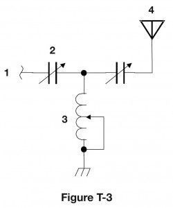
The circuit shown in Figure T3 is the output circuit of a transmitter. Component 3 in figure T3 is a variable inductor. (T6C10)
There are two variable capacitors in this circuit—component 2 and the unlabeled component. A capacitor is used together with an inductor to make a tuned circuit. (T6D08)
Component 4 in figure T3 is an antenna. (T6C11)
An inductor and a capacitor connected in series or parallel to form a filter is a simple resonant or tuned circuit. (T6D11) When the capacitor and inductor are connected in series, the circuit has a very low impedance at the resonant frequency. When the capacitor and inductor are connected in parallel, the circuit has a very high impedance at the resonant frequency.
Leave a Reply