
No questions changed in this section, but the title has. Instead of being titled, “Power supplies; transmitters and receivers; filters; schematic drawing symbols,” it’s now titled simply, “Power supplies and schematic symbols.”
Power supplies and schematic symbols
Power supplies are devices that convert AC power to the DC voltages needed to power amateur radio equipment. There are two main types of power supplies available: linear power supplies and switching power supplies.
Linear supplies use a transformer to transform the voltage up or down, a rectifier to convert the AC voltage to a DC voltage, and capacitors and inductors to smooth the output voltage. The rectifier in a linear supply may be a half-wave rectifier, a full-wave rectifier, or a bridge rectifier.
180 degrees is the portion of the AC cycle that is converted to DC by a half-wave rectifier (G7A05). The peak-inverse-voltage across the rectifiers in a half-wave power supply is two times the normal peak output voltage of the power supply. (G7A04)
360 degrees is the portion of the AC cycle that is converted to DC by a full-wave rectifier (G7A06). The peak-inverse-voltage across the rectifiers in a full-wave bridge power supply is equal to the normal peak output voltage of the power supply. (G7A03). A series of DC pulses at twice the frequency of the AC input is the output waveform of an unfiltered full-wave rectifier connected to a resistive load (G7A07).
The output of a rectifier connects to a filter made up of capacitors and inductors. Capacitors and inductors are used in a power-supply filter network (G7A02). A component often found across the output of a power supply is a power-supply bleeder resistor. A power supply bleeder resistor is a safety feature in that it discharges the filter capacitors. (G7A01). This resistor is normally a very high value and draws very little current during normal operation.
Switching, or switched-mode power supplies are now being sold by many vendors. One advantage of a switched-mode power supply as compared to a linear power supply is that high frequency operation allows the use of smaller components (G7A08). One disadvantage is that the circuits are much more complex than linear power supply circuits.
When designing or troubleshooting radios, amateur radio operators use schematic diagrams to describe circuits. Various symbols represent the different types of components. A typical schematic is shown in Figure G7-1.
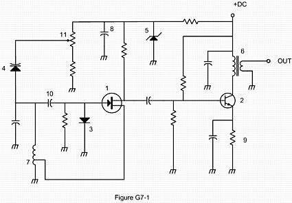
Symbol 1 in figure G7-1 represents a field effect transistor. (G7A09)
Symbol 5 in figure G7-1 represents a Zener diode. (G7A10)
Symbol 2 in figure G7-1 represents an NPN junction transistor. (G7A11)
Symbol 6 in Figure G7-1 represents a multiple-winding transformer. (G7A12)
Symbol 7 in Figure G7-1 represents a tapped inductor. (G7A13)
Leave a Reply