
On July 1, 2020, this post will be obsolete. See the corresponding post from my 2020 version of No Nonsense Extra Class License Study Guide.
Five questions were eliminated from this section, making it a little easier….Dan
E7G – Active filters and op-amps: active audio filters; characteristics; basic circuit design; operational amplifiers
Operational amplifiers, or op-amps for short, are very versatile components. They can be used to build amplifiers, filter circuits, and many other types of circuits that do analog signal processing.
An integrated circuit operational amplifier is a high-gain, direct-coupled differential amplifier with very high input and very low output impedance. (E7G12) The typical input impedance of an integrated circuit op-amp is very high. (E7G03) The typical output impedance of an integrated circuit op-amp is very low. (E7G01)
The gain of an ideal operational amplifier does not vary with frequency. (E7G08) Most op amps aren’t ideal, though. While some modern op amps can be used at high frequencies, many of the older ones can’t be used at frequencies above a couple of MHz.
Ideally, with no input signal, there should be no voltage difference between the two input terminals, and the output voltage should also be zero. Since no electronic component is ideal, there will be a voltage between these two terminals. We call this the input offset voltage. Put another way, the op-amp input-offset voltage is the differential input voltage needed to bring the open-loop output voltage to zero. (E7G04)
Because they are active components—that is to say that they amplify—filters made with op amps are called active filters. The most appropriate use of an op-amp active filter is as an audio filter in a receiver. (E7G06). The values of capacitors and resistors external to the op-amp primarily determine the gain and frequency characteristics of an op-amp RC active filter.
Ringing is one undesirable characteristic of an op-amp filter. One effect of ringing in a filter is that undesired oscillations to be added to the desired signal. (E7G02) One way to prevent unwanted ringing and audio instability in a multi-section op-amp RC audio filter circuit is to restrict both gain and Q. (E7G05)
Calculating the gain of an op amp circuit is relatively straightforward. The gain is simply RF/Rin. In figure E7-4 below, Rin = R1. Therefore, the magnitude of voltage gain that can be expected from the circuit in Figure E7-4 when R1 is 10 ohms and RF is 470 ohms is 470/10, or 47. (E7G07) The absolute voltage gain that can be expected from the circuit in Figure E7-4 when R1 is 1800 ohms and RF is 68 kilohms is 68,000/1,800, or 38. (E7G10) The absolute voltage gain that can be expected from the circuit in Figure E7-4 when R1 is 3300 ohms and RF is 47 kilohms is 47,000/3,300, or 14. (E7G11)
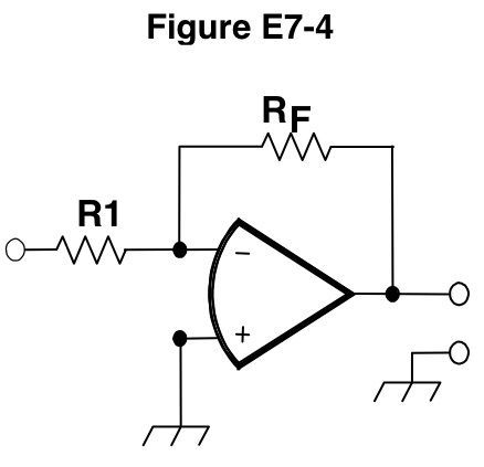
-2.3 volts will be the output voltage of the circuit shown in Figure E7-4 if R1 is 1000 ohms, RF is 10,000 ohms, and 0.23 volts dc is applied to the input. (E7G09) The gain of the circuit will be 10,000/1,000 or 10, and the output voltage will be equal to the input voltage times the gain. 0.23 V x 10 = 2.3 V, but since the input voltage is being applied to the negative input, the output voltage will be negative.
Leave a Reply