
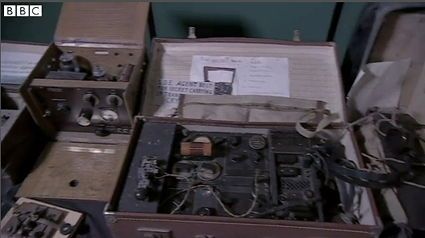
The unassuming Buckinghamshire village of Whaddon was the center of radio communications for the British in WW II. This BBC video celebrates the role that Whaddon played in helping the Allies win the war.
![]()
![]() Strange Beacons @StrangeBeacons
Strange Beacons @StrangeBeacons
Links to a Large Collection of Online WebSDR Radios: websdr.org #SoftwareDefinedRadio #shortwave pic.twitter.com/7kR95VWbKb
 I’ve started teaching some basic electronics classes at the Ann Arbor District Library. They recently setup a makerspace they’re calling The Secret Lab and hired a guy named Steve Teeri to run it. I got hooked up with Steve after I inquired about the possibility of teaching some basic electronics classes. As it turned out, they had recently gotten to the point where they could start doing things like electronics classes in the Secret Lab so my inquiry had come at a fortuitous moment. I’ve since become the de-facto electronics/ham radio consultant to the library.
The first class we held was on how to use a digital multimeter. Five people showed up, and it turned into a class on circuits as much as a class on how to use a DMM. Overall, it went pretty well, and we followed that up with a class on how to use an oscilloscope.
This evening, we held a class on basic transistor circuits. This evening, we had nine people show up. There were a couple of older guys, three younger guys, two women, one who brought her two kids. The kids were eight and ten.
Initially, I had planned to have the students breadboard two circuits – a simple switch circuit and a common-emitter amplifier circuit. Both of these circuits can be found on the sheet below.
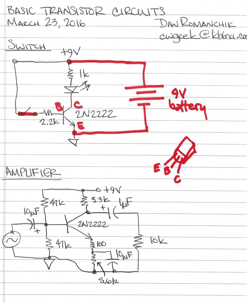
I figured that we’d be able to blow through the switch circuit, then dig into the amplifier circuit. WRONG! It took us nearly the entire class for everyone to get the switch circuit to work.
Some of it was my fault. First of all my schematic was lacking. It was a schematic that I got off the Internet, and while it was correct, it wasn’t detailed enough. As you can see from the red ink above, there were several omissions and errors:
An added complication was that the resistors that the library had purchased had blue bodies and very thin color bands. The result was that it was really difficult to really read the color code. At first, I thought it was just me and my failing eyesight, but I was relieved when one of the students had the same complaint. We actually had to dig out the multimeters and measure the resistors to make sure that we had the right ones.
Another reason that it took us so long is that I had to teach the students some really basic stuff, even before we got to the point where they could put the circuits together. This included the resistor color code and how to use the proto boards that we were using. This was certainly OK, but I hadn’t anticipated having to do that.
After about 45 minutes, all of the circuits were built, and the LEDs were lit. I asked them to disconnect the 2.2 k resistor to demonstrate how removing the base current turns off the transistor, and I think they all got that idea. I also explained how in practice that 2.2 k resistor wouldn’t be connected directly to a power supply but to perhaps an Arduino’s digital output. I also mentioned that instead of just turning an LED on and off, we might use the transistor to do some real work like switch a relay on and off. I think they got those ideas, too.
One guy asked how much current that the 2N2222 could switch. I had brought along with me a 2N2222 data sheet, and we looked up the maximum collector current for a 2N2222 (1.0 A). We then discussed how running the transistor at its maximum current rating might not be a good idea.
There was just enough time to go over the amplifier circuit quickly. Fortunately, I had the foresight to bring my own protoboard with the amplifier circuit already assembled on it. I quickly hooked up the scope probes, the signal generator, and the 9 V battery, and demonstrated how the circuit turned a 100 mV signal into a 2 V signal. For those who were interested, I was also able to talk a little bit about biasing.
So, the first thing that I take away from this experience is that I really need to gear down the level of the presentations. Second, I need to be a little more explicit with my instructions to students.
I’m hoping to do a lot more with the Ann Arbor District Library. I think that perhaps the next class will be an Arduino Basics class. At some point, too, I’ll want to reprise my DMM and oscilloscope class. I really love it that the library is giving me the opportunity to do this.
On July 1, 2020, this post will be obsolete. See the corresponding post from my 2020 version of No Nonsense Extra Class License Study Guide.
E7A – Digital circuits: digital circuit principles and logic circuits: classes of logic elements; positive and negative logic; frequency dividers; truth tables
Digital circuits are used for a variety of functions in modern amateur radio equipment. Unlike analog circuits, the output voltage of an ideal digital circuit can only be one of two values. One of these voltages—normally a positive voltage—represents a digital 1. The other value—normally near 0 V—represents a digital 0.
This type of logic is generally called positive logic. Positive Logic is the name for logic which represents a logic “1” as a high voltage. (E7A11) The logic may be reversed, though. That is to say that a high voltage may represent a logic 0. Negative logic is the name for logic which represents a logic “0” as a high voltage. (E7A12)
The microcomputers that control today’s transceivers are very complex digital circuits. These complex digital circuits are made by combining many smaller building blocks called logic gates. These gates perform basic digital logic functions.
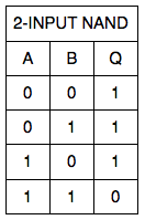
One of the most basic digital circuits in the NAND gate. The logical operation that a NAND gate performs is that it produces a logic “0” at its output only when all inputs are logic “1.” (E7A07)
This logical operation can be described by a truth table. A truth table is a list of inputs and corresponding outputs for a digital device. (E7A10) Table E7-1 shows a truth table that describes the operation of a two-input NAND gate. A and B are the two inputs; Q is the output.
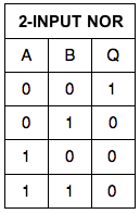
Other types of gates perform different logical functions. The logical operation that a NOR gate performs is that it produces a logic “0” at its output if any or all inputs are logic “1.” (E7A08) Table E7-2 shows a truth table that describes the logical operation of a NOR gate.
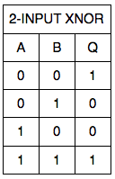
The logical operation that is performed by a two-input exclusive NOR gate is that it produces a logic “0” at its output if any single input is a logic “1.” (E7A09) Table E7-3 shows a truth table that describes the logical operation of an XNOR gate.
Flip-flops are circuits that are made from combinations of logic gates. By “latching” the state of an input at a particular time, a flip-flop can be said to have memory. A D flip-flop, and its truth table is shown in the figure below.
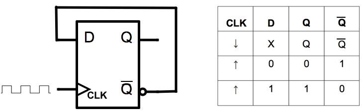
As shown, the output changes only on the rising edge of the clock (CLK) signal. That is to say, when the signal goes from 0 to 1. If D = 1, Q = 1. If D = 0, then Q = 0. The other output, denoted by a bar over the Q, is the inverse of Q.
When a D flip-flop is connected as shown in the figure—with the inverted output connected to the D input—a flip-flop can divide the frequency of a pulse train by 2. (E7A03) You can connect the Q output to a second flip-flop to divide the frequency even further. Consequently, 2 flip-flops are required to divide a signal frequency by 4. (E7A04)
By connecting a number of flip-flops together, and resetting the circuit once ten pulses have been input, you can build a decade counter. The function of a decade counter digital IC is to produce one output pulse for every ten input pulses. (E7A02)
A flip-flop is a bistable circuit. (E7A01) That means its output is stable in either state. A monostable circuit is one that is stable in one state, but not the other. One characteristic of a monostable multivibrator is that it switches momentarily to the opposite binary state and then returns, after a set time, to its original state.(E7A06) A trigger pulse causes the monostable vibrator to switch to the unstable state, and it stays in that state for a set period, no matter how long the trigger pulse. An astable multivibrator is a circuit that continuously alternates between two states without an external clock. (E7A05) In other words, it is an oscillator.
On July 1, 2020, this post will be obsolete. See the corresponding post from my 2020 version of No Nonsense Extra Class License Study Guide.
Two questions—E6F13 and E6F14—about LCD displays were added to this section. The other questions were unchanged…Dan
E6F: Optical components: photoconductive principles and effects, photovoltaic systems, optical couplers, optical sensors, and optoisolators; LCDs
The photovoltaic effect is the conversion of light to electrical energy. (E6F04) In a photovoltaic cell, electrons absorb the energy from light falling on a photovoltaic cell. (E6F12) The electrons then become free electrons.
The most common type of photovoltaic cell used for electrical power generation is silicon. (E6F10) The approximate open-circuit voltage produced by a fully-illuminated silicon photovoltaic cell is 0.5 V. (E6F11) The efficiency of a photovoltaic cell is the relative fraction of light that is converted to current. (E6F09)
Photoconductivity is a similar phenomenon. Photoconductivity is the increased conductivity of an illuminated semiconductor. (E6F01) The conductivity of a photoconductive material increases when light shines on it. (E6F02) A crystalline semiconductor is the material that is affected the most by photoconductivity. (E6F06)
A device that uses the phenomenon of photoconductivity is the optoisolator. The most common configuration of an optoisolator or optocoupler is an LED and a phototransistor. (E6F03) Optoisolators are often used in conjunction with solid state circuits when switching 120 VAC because optoisolators provide a very high degree of electrical isolation between a control circuit and the circuit being switched. (E6F08)
A similar device is the solid-state relay. A solid state relay is a device that uses semiconductor devices to implement the functions of an electromechanical relay. (E6F07)
Optical shaft encoders are another device that rely on photoconductivity. An optical shaft encoder is a device which detects rotation of a control by interrupting a light source with a patterned wheel. (E6F05) Optical shaft encoders are used to detect when an operator turns a knob on an amateur radio transceiver.
Liquid crystal displays
A liquid crystal display (LCD) is a display utilizing a crystalline liquid and polarizing filters which becomes opaque when voltage is applied. (E6F13) One thing that is true of LCD displays is that they may be hard to view through polarized lenses. (E6F14)
 Make great oscilloscope measurements. In oscilloscopes today, making a good signal measurement is easy. However, making a great measurement takes some expertise.
Op amp basics: Small signal bandwidth and overall performance. It is rare to find an op amp data sheet without a bandwidth number on the front page. Because small signal bandwidth is the largest number, this is usually the number featured most prominently. A good question, though, is how important is this number and how does it relate to other device performance metrics?
The quest for the ultimate vacuum tube. In July 1962, the Telstar 1 satellitetook an enormous leap toward the globally connected world we now take for granted. It relayed from space, for the first time ever, live television images and telephone calls between continents: specifically, a ground station in Andover, Maine, and other stations in England and France. It accomplished this feat thanks to a microwave repeater that had at its heart a slight but powerful vacuum device known as a traveling-wave tube. The 30-centimeter-long,glass-walled electron tube was at the time the only device capable of boosting a broadband television signal with enough power to cross an ocean. Solid-state devices just weren’t up to the task. More than a half century later, traveling-wave-tube amplifiers still dominate satellite communication. That’s right—your ultrahigh-definition satellite TV and satellite radio come to you courtesy of vacuum tubes in space.
From the Rockwell Collins website…
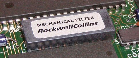
Rockwell Collins Filter Products specializes in designing mechanical filters to meet your unique and evolving requirements. We produce two different types of mechanical filters. For frequencies between 100 kHz and 700 kHz, we create filters made from rods resonating in a torsion mode. For frequencies below 100 kHz, we use flexure mode bar resonators. Our filters can achieve bandwidths from 0.05 to 5 percent.
Over the past several years, we have seen a dramatic reduction in demand for narrowband analog filters. Due to this and other economic reasons, Filter Products will be discontinuing its mechanical filter products in the near future.
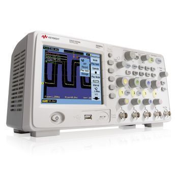
 DIY Makers, Hobbyists, and Experimenters Get Professional Software. National Instruments has come out with a $49 version of LabView. According to the article, “Called the LabVIEW Home Bundle, this is a fully operational version of the core NI product that can be used to speed up and simplify experimentation by making programming less of a problem.” I’m not having much success with the software bundled with my new digital scope (more on that later, but it’s been very disappointing), and I know LabView is quality software, so I’m seriously thinking about purchasing this package. NOTE: If you’re a student, you can buy a Student Edition of LabView for as little as $20!
Q&A: Digi-Key’s Larson Looks Back—And Ahead. I found this interesting as DigiKey actually started out as a place for hobbyists to get parts. The CEO says, “In the early days, Ron was a graduate student at the University of Minnesota, and he was a very active ham radio enthusiast. While he was still in school, he put together a kit [of electronic parts] for sending Morse code, and he would sell these kits at ham radio fairs.” Now, of course, it’s a major electronic components distributor.
Understanding Mixers and Their Parameters. While written for engineers, not radio amateurs, it’s not heavy on the math and just might give you a better understanding of mixers and some of the terminology associated with them.
I have a friend runs a math summer camp here in Ann Arbor at the University of Michigan for smart young people. I’ll write more about this later, but here’s how he describes it:
We build a machine that will allow the user to enter data on a breadboard, using nothing more sophisticated than switches, logic gates, and flip flops, and have the result be a tweet that includes a picture. Our class of 16 students will each work on a portion of the machine, and at the end we’ll put it all together.
Since its inception, I’ve been the camp’s “electronics consultant.” I loan them a power supply every year, and have, in the past helped them with various electronics questions.
This year, my friend asked me how to debounce a switch. They use a pushbutton switch to clock in data, and as you can imagine, if the switch isn’t debounced properly, they get multiple clocks, which screw up the operation of their machine.
I understand debouncing, but to be honest, I never really had to design a debounce circuit. So, I did a little Googling and found, “A Guide to Debouncing” by Jack G. Ganssle. Ganssle. This 22-page monograph really gets into the theory of why switches bounce and describes several different ways to debounce a switch. One of the simplest ways to do this—and probably the most appropriate method for this project—is a simple RC circuit:
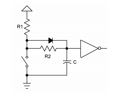
Basically, the way this works is that C charges to VCC, and when you throw the switch to take the logic circuit input low, C discharges. You set the values of C and R2 such that the time constant is at least as long as the time during which the switch bounces. Ganssle describes how to do this, and he’s even made some measurements on how much time you need for the switch to quit bouncing.
The diode in the circuit is optional. Its function is to speed up the capacitor charging once the switch is released.
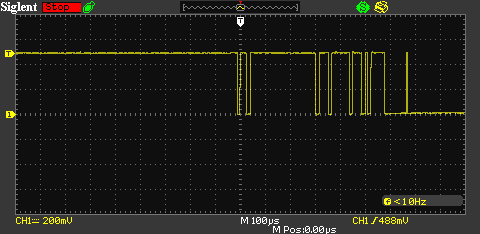
I dug though my junk box and found all the components that I needed to breadboard the circuit, then used my fancy, new digital scope to observe both the bouncy switch input and the debounced circuit output. Here is the bouncy switch:
And here is the debounced waveform:
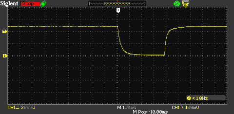
I know that this is a very simple circuit, and that I really shouldn’t be surprised that it works, but I like it when simple things work. The result here is that my friend’s summer camp will have a stable clock input, and the circuit is something that he can easily explain to the kids. It should be as educational for them as it was for me.