
 I need an illustrator to do the cover for my updated Extra Class study guide. The fellow who did the covers for the latest Tech and General study guides has taken a full-time job and doesn’t have the time to do one for the Extra. Preferably, I’d like someone who could do it in a style similar to the current covers. If that’s you, or someone you know, email me.
study guides
Anyone want to help with the 2024 Extra Class study guide?
 As many of you know, the U.S. amateur radio license question pools get updated every four years. In 2024, it’s the Extra Class question pool’s turn. The National Conference of Volunteer Examiner Coordinators (NCVEC) released the new question pool on December 7, 2023, and surprisingly, I’ve already started on updating the No Nonsense Extra Class License Study Guide. I’m already done with the first three (out of ten) chapters.
What I’m looking for is some help with the proofreading and editing. In the past, I’ve hired professional proofreaders, but honestly, they didn’t do a very good job. One of them was even a licensed radio amateur.
The first part of the job would be to check that I’ve included all of the questions in the question pool for a particular chapter. Believe it or not, I’ve missed questions in the past. The second would be to critique the text to help ensure that I’m explaining the answer to a question properly.
I don’t expect you to do it for nothing, but I’m not sure what proper compensation would be. We can discuss this.
If you’re interested in helping me out, please email me at [email protected]. You could also leave a comment below. Thanks!
The 2023 version of the No Nonsense General Class License Study Guide is now available!
Well, it took a bit longer than I expected, but the updated version of my General Class study guide is now available. You’ll find the PDF version here on this website, and the Kindle version on the Amazon website. The print version should be available by the end of the week, and I’ll be recording the audiobook over the next several weeks.
There were actually quite a few changes to this year’s question pool. According to HamStudy.org, there were
- 80 removed questions,
- 57 new questions, and
- 119 updated questions
Overall, the number of questions was reduced from 454 to 431.
Some of the deletions I don’t really understand. For example, they deleted the three questions that asked about the maximum signal rates allowed for data emissions on various bands. Perhaps they were anticipating rules changes, although I’m not sure those are going to happen any time soon.
One thing that I will applaud them for is that they have clarified the language of many of the questions and answers. These clarifications will make it easier for students.
It’s nice to be appreciated
 I’ve gotten some nice feedback from readers in the past couple of days, and I thought I’d share them with you. Comments like these really keep me motivated.
Kyle wrote:
Just wanted to drop you a line and say thanks for your great books. After being a Tech for 18 years, I finally got around to getting my General because of your book. Now I’m working on my Extra! Thanks for the resource. You’ve really opened up the hobby for me. Over the weekend, I activated my first summit for SOTA and really enjoyed it. Hope all is well with you and thanks again.
Eric writes:
I read your study guide and took my Technician exam today and got 35 for 35. Great book, easy to read. It helped me immensely. Just wanted to say thank you.
Del writes:
I just wanted to thank you for the free Technician’s PDF and the very modestly priced Anki “smaht” flash cards. With the two of those and about 4 weeks of study I just passed my Technician’s Exam this morning. No call sign yet, of course, but my smile will suffice in the meantime.
Jay writes:
I passed!!!!! Wooooohooooo! You made the difference. Your book is what put me here. Thank you.
Operating Notes: A comment from a reader
A couple of days ago, I worked a fellow who had used my study guide to get back into ham radio. Yesterday, I got this email:
Roughly five years ago my wife and I were downsizing and decided to sell our house. I was googling something about homes and for an unknown reason, a link was presented to me about a Technician Class PDF study guide. I hadn’t had my license for twenty years and had no interest in ham radio until I looked at the study guide, your study guide.
At that time, I had recently lost my father to brain cancer. His call was NZ3U and before that, he was WA3MWT. Ham radio was a huge part of his life and mine as a youngster. I guess I was feeling nostalgic at the time and also feeling guilty that he and I no longer shared the hobby before he passed. When I looked over the study guide, I realized I knew most of the material. So, I used your guide and decided to go for the exam. You know the rest of the story. I did it to satisfy my dad’s warning to me when I let my license lapse. He said “You’ll regret it someday” and he was right.
Shortly after I passed the exam and got my General ticket and we moved to a location in the woods. A perfect spot for wire antennas. So I threw up a home made dipole, bought a IC7200 and was up and running. The rest is history.
So in short, your study guide was solely responsible for my return to ham radio. That’s another reason it’s always a thrill to work you.
How cool is that?
SKN with the Flex
On New Year’s Eve and New Year’s Day, I participated for a little while in Straight Key Night (SKN). Overall, I made five contacts before my wrist gave out on me. As I was making contacts, though, it occurred to me that it was somewhat amusing to be using what is arguably the most modern radio on the market with nearly the most ancient mode.
Should I tell this guy about his signal?
One of the signals that I encountered on Straight Key Night was the signal below. This is the widest signal I’ve ever seen on the Flex panadapter. As you can see, it’s nearly 4 kHz wide, while the others are more like 100 Hz wide.
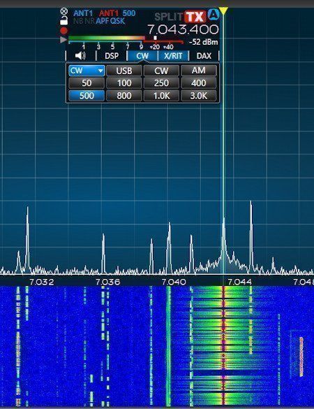
My question is, should I send the guy this screenshot? I’m thinking that if I were him, I’d want to know that perhaps something is wrong with my transmitter.
2019 No Nonsense General Class Study Guide: Operating Procedures, part I

 Phone operating procedures, USB/LSB utilization conventions, procedural signals, breaking into a QSO in progress, VOX operation
On the HF bands, the most common mode used for voice communications is single sideband, or SSB. SSB is a type of amplitude modulation, or AM. In the process of amplitude modulation, a transmitter generates an upper sideband and a lower sideband, in addition to the carrier signal. Back in the early days of radio, a smart guy figured out all of the information in a voice signal is carried in one of the sidebands, and that it would be more efficient to filter out the carrier and one of the sidebands and put all of the power of a radio signal into a single sideband. In addition to voice communications, SSB is also used to transmit digital information on the HF bands.
QUESTION: Which mode of voice communication is most commonly used on the HF amateur bands? (G2A05)
ANSWER: Single sideband
QUESTION: Which of the following statements is true of the single sideband voice mode? (G2A07)
ANSWER: Only one sideband is transmitted; the other sideband and carrier are suppressed
QUESTION: Which of the following is an advantage when using single sideband, as compared to other analog voice modes on the HF amateur bands? (G2A06)
ANSWER: Less bandwidth used and greater power efficiency
A single sideband signal can be either upper sideband signal can be either upper sideband (USB) or lower sideband (LSB), but USB is the most commonly used sideband. USB is used almost exclusively on frequencies above 14 MHz, including the VHF and UHF bands, as well as on the 60 m band, while LSB is used on the 160 m, 75 m, and 40 m bands. There’s no particular technical reason for this. It’s just current amateur practice to do so.
QUESTION: Which sideband is most commonly used for voice communications on frequencies of 14 MHz or higher? (G2A01)
ANSWER: Upper sideband
QUESTION: Which mode is most commonly used for voice communications on the 17-meter and 12-meter bands? (G2A04)
ANSWER: Upper sideband
QUESTION: Which of the following is most commonly used for SSB voice communications in the VHF and UHF bands? (G2A03)
ANSWER: Upper sideband
QUESTION: Which of the following modes is most commonly used for voice communications on the 160-meter, 75-meter, and 40-meter bands? (G2A02)
ANSWER: Lower sideband
QUESTION: Why do most amateur stations use lower sideband on the 160-meter, 75-meter, and 40-meter bands? (G2A09)
ANSWER: It is good amateur practice
To establish a contact on the HF bands, you can call CQ or reply to a CQ. Sometimes you’ll hear stations calling “CQ DX” instead of simply CQ. If the station calling CQ DX is located in the contiguous 48 states, then the operator is looking to make contacts outside of the U.S., and if you’re not outside of those states, it is good operating procedure not to answer that call.
QUESTION: Generally, who should respond to a station in the contiguous 48 states who calls “CQ DX”? (G2A11)
ANSWER: Any stations outside the lower 48 states
Another way to establish a contact is to break into a conversation that’s already in progress. To do this, simply say your callsign when there is a lull in the conversation.
QUESTION: What is the recommended way to break in to a phone contact? (G2A08)
ANSWER: Say your call sign once
Before making contacts, make sure that you set the microphone gain to the appropriate level. Setting the microphone gain too low will reduce the output power of your transmitter. Setting it too high will result in distorted audio and spurious emissions. Refer to your transceiver’s user manual for instructions on how to do this.
QUESTION: What control is typically adjusted for proper ALC setting on an amateur single sideband transceiver? (G2A12)
ANSWER: Transmit audio or microphone gain
When operating SSB, many amateurs like to use the VOX, or voice-operated control, instead of push-to-talk, or PTT, operation. Using VOX frees up an operator’s hands to do things like adjust controls or log contacts.
QUESTION: Which of the following statements is true of voice VOX operation versus PTT operation? (G2A10)
ANSWER: It allows “hands free” operation
Operating courtesy; band plans; emergencies, including drills and emergency communications
Whenever you’re operating, courtesy should always be a consideration when selecting a frequency. The courteous thing to do is to select an operating frequency so that you do not interfere with other stations operating on nearby frequencies. You can avoid interference with other stations by ensuring that the frequency you want to use is not already in use. Remember that on many HF bands you may only be able to hear one station and not the other, so before calling, ask if the frequency is in use.
When operating phone, you simply ask if the frequency is in use. When operating CW, you send the Q signal QRL?
QUESTION: What is a practical way to avoid harmful interference on an apparently clear frequency before calling CQ on CW or phone? (G2B06)
ANSWER: Send “QRL?” on CW, followed by your call sign; or, if using phone, ask if the frequency is in use, followed by your call sign
QUESTION: What does the Q signal “QRL?” mean? (G2C04)
ANSWER: “Are you busy?”, or “Is this frequency in use?”
Another way to avoid interference is to follow the voluntary band plan for the mode you’re using. For example, most band plans call for SSTV operation around 14.230 MHz. So, if you’re operating SSB, you probably want to avoid that frequency.
QUESTION: Which of the following complies with good amateur practice when choosing a frequency on which to initiate a call? (G2B07)
ANSWER: Follow the voluntary band plan for the operating mode you intend to use
Some band plans may denote a frequency or small band of frequencies as the DX window for that band. What that means is that U.S.. stations are not to call inside that window to allow DX stations to be heard. In the 6 m band, the DX window is 50.1 – 50.25 MHz.
QUESTION: What is the voluntary band plan restriction for U.S. station transmitting within the 48 contiguous states in the 50.1 to 50.125 MHz band segment? (G2B08)
ANSWER: Only contacts with stations not within the 48 contiguous states
Another thing you should do to avoid interference is to make sure that the frequency you wish to use is not too close to other stations.
QUESTION: When selecting an SSB transmitting frequency, what minimum separation should be used to minimize interference to stations on adjacent frequencies? (G2B05)
ANSWER: Approximately 3 kHz
QUESTION: When selecting a CW transmitting frequency, what minimum separation should be used to minimize interference to stations on adjacent frequencies? (G2B04)
ANSWER: 150 to 500 Hz
Band conditions can change during the course of a contact. When this happens, you may find that your contact is now being interfered with by stations that you could not hear previously or that you are interfering with stations that could not hear you previously. Should this occur, the courteous thing to do is to simply move your contact to another open frequency.
QUESTION: What is good amateur practice if propagation changes during a contact and you notice interference from other stations on the frequency? (G2B03)
ANSWER: Attempt to resolve the interference problem with the other stations in a mutually acceptable manner
One thing to keep in mind is that no one “owns” a frequency, no matter how long it has been their practice to use the frequency. Even nets don’t have the right to kick you off a frequency.
QUESTION: Which of the following is true concerning access to frequencies in non-emergency situations? (G2B01)
ANSWER: Except during FCC declared emergencies, no one has priority access to frequencies, common courtesy should be a guide
It’s also important to know what to do if you hear a station in an emergency situation. While the rules are very strict regarding normal operation of an amateur radio station, an amateur station is allowed to do just about anything to assist another station in distress during an actual emergency. This means using frequencies outside of the amateur bands and using high power should the situation require it.
QUESTION: When is an amateur station allowed to use any means at its disposal to assist another station in distress? (G2B10)
ANSWER: At any time during an actual emergency
QUESTION: What frequency should be used to send a distress call? (G2B11)
ANSWER: Whichever frequency has the best chance of communicating the distress message
Helping that station in distress should become your first priority. The first thing you should do if you are communicating with another amateur station and hear a station in distress break in is to figure out how to help them.
QUESTION: What is the first thing you should do if you are communicating with another amateur station and hear a station in distress break in? (G2B02)
ANSWER: Acknowledge the station in distress and determine what assistance may be needed
In certain emergencies, government officials might activate the Radio Amateur Civil Emergency Service (RACES), a protocol created by the Federal Emergency Management Agency (FEMA) and the Federal Communications Commission. To be a part of RACES, you must be a licensed radio amateur and be certified by a civil defense agency.
QUESTION: Who may be the control operator of an amateur station transmitting in RACES to assist relief operations during a disaster? (G2B09)
ANSWER: Only a person holding an FCC issued amateur operator license
CW operating procedures and procedural signals, Q signals and common abbreviations, full break in
When establishing a CW contact with another station, the sending and receiving stations should always synchronize their speed. You might be a real speed demon, but if you want to answer a CQ being sent at a speed much slower than the speed at which you can send and receive, then you should slow down to accommodate the slower operator. Likewise, if you’re not comfortable sending and receiving at the speed of a station calling CQ, reply at a lower speed. A good operator will then slow down to accommodate you.
QUESTION: What is the best speed to use when answering a CQ in Morse code? (G2C05)
ANSWER: The fastest speed at which you are comfortable copying, but no faster than the CQ
When answering a CQ, you should set the frequency of your transceiver so that it matches the frequency of the sending station. We call this process “zero beating.” One reason for doing this is that it makes it easier for the calling station to find you. Another reason is that your contact will require less bandwidth.
QUESTION: What does the term “zero beat” mean in CW operation? (G2C06)
ANSWER: Matching the transmit frequency to the frequency of a received signal
After establishing contact, it’s customary to send the other station a signal report. This report consists of three numbers that correspond to the readability, strength, and tone of the signal. Hams sometimes call this the RST report. When appropriate, an operator may append a letter to the RST report. For example, to denote that a signal has a chirp, you would append the letter “C.”
QUESTION: When sending CW, what does a “C” mean when added to the RST report? (G2C07)
ANSWER: Chirpy or unstable signal
During the course of a CW contact, it’s good practice to use Q signals to shorten the number of characters that you must send and which the receiving station needs to receive. Q signals are three letter combinations that begin with the letter “Q.” There are many different Q signals, but you only need to know four of them to pass the test.
QUESTION: What should you do if a CW station sends “QRS?” (G2C02)
ANSWER: Send slower
QUESTION: What does the Q signal “QSL” mean? (G2C09)
ANSWER: I acknowledge receipt
QUESTION: What does the Q signal “QRN” mean? (G2C10)
ANSWER: I am troubled by static
QUESTION: What does the Q signal “QRV” mean? (G2C11)
ANSWER: I am ready to receive messages
CW operators also use what are called prosigns. Prosigns can indicate what an operator intends to do or calls for the other operator to do something. For example, the prosign “K” is an invitation to other stations to begin transmitting. “KN” is also an invitation to transmit, but only a specific station, usually the station with which a station is already in contact.
QUESTION: What does it mean when a CW operator sends “KN” at the end of a transmission? (G2C03)
ANSWER: Listening only for a specific station or stations
QUESTION: What prosign is sent to indicate the end of a formal message when using CW? (G2C08)
ANSWER: AR
When operating CW, some hams simply mute their receivers during a transmission. The problem with this approach is that the other operator cannot break in to make a comment. Another problem is that you can’t hear if another station is interfering with your transmission. To get around these problems, hams use “break-in mode,” or QSK.
QUESTION: Which of the following describes full break-in telegraphy (QSK)? (G2C01)
ANSWER: Transmitting stations can receive between code characters and elements
2019 No Nonsense General Class Study Guide: Amateur Radio Practices, part II
Interference with consumer electronics, grounding, DSP
At some point or another, your amateur radio station will interfere with a radio or television set, a PA system, or a telephone. A SSB transmission generally causes some kind of humming, while a CW transmission can cause humming or clicking. Sometimes this may be your fault, other times it may be the fault of the device. In either case, you should do everything you can to eliminate this interference.
QUESTION: What sound is heard from an audio device or telephone if there is interference from a nearby single sideband phone transmitter? (G4C03)
ANSWER: Distorted speech
QUESTION: What is the effect on an audio device when there is interference from a nearby CW transmitter? (G4C04)
ANSWER: On-and-off humming or clicking
Fortunately, there are many things you can do to reduce or eliminate the interference. For example, you might connect a bypass capacitor across speaker leads to reduce interference to an audio device. To reduce RF picked up by audio cables, you might use a snap-on ferrite choke. I often advise amateurs to have a handful of these on hand for this type of application.
QUESTION: Which of the following might be useful in reducing RF interference to audio frequency devices? (G4C01)
ANSWER: Bypass capacitor
QUESTION: Which of the following would reduce RF interference caused by common-mode current on an audio cable? (G4C08)
ANSWER: Placing a ferrite choke around the cable
Proper grounding is also important to reduce interference. Rather than connecting the grounds in a daisy-chain fashion, you should connect them all to a single point. This will help you avoid ground loops, which can cause a hum on your phone signal.
QUESTION: How can a ground loop be avoided? (G4C09)
ANSWER: Connect all ground conductors to a single point
QUESTION: What could be a symptom of a ground loop somewhere in your station? (G4C10)
ANSWER: You receive reports of “hum” on your station’s transmitted signal
When grounding RF equipment, keep ground cables short and direct to prevent high-impedance or resonant ground connections. A long ground wire may present a high impedance at HF frequencies and instead of grounding station equipment enclosures may cause high voltages to be present. This, in turn, may cause operators to receive an RF burn when touching the enclosure. Also be sure to “bond” the enclosures together to prevent any potential differences that can cause hazard voltages, or “hot spots,” between the enclosures.
QUESTION: What effect can be caused by a resonant ground connection? (G4C06)
ANSWER: High RF voltages on the enclosures of station equipment.
QUESTION: What might be the problem if you receive an RF burn when touching your equipment while transmitting on an HF band, assuming the equipment is connected to a ground rod? (G4C05)
ANSWER: The ground wire has high impedance on that frequency
QUESTION: Why must the metal enclosure of every item of station equipment be grounded? (G4C13)
ANSWER: It ensures that hazardous voltages cannot appear on the chassis
QUESTION: What technique helps to minimize RF “hot spots” in an amateur station? (G4C11)
ANSWER: Bonding all equipment enclosures together
A common complaint of amateur radio operators is electrical noise that seems to be on every band. This may be caused by arcing in a power line transformer or at some other connection.
QUESTION: Which of the following could be a cause of interference covering a wide range of frequencies? (G4C02)
ANSWER: Arcing at a poor electrical connection
One way to eliminate noise is to use digital signal processor, or DSP. Modern amateur radio transceivers have built-in DSPs that operate at IF frequencies. DSP filters generally work better than analog filters.
QUESTION: Which of the following is an advantage of a receiver DSP IF filter as compared to an analog filter? (G4C12)
ANSWER: A wide range of filter bandwidths and shapes can be created
Speech processors, S meters, sideband operation near band edges
Speech processors can be very useful when operating SSB. Speech processors increase the average power output of an SSB transmitter, thereby increasing the intelligibility of the signal when conditions are poor.
QUESTION: What is the purpose of a speech processor as used in a modern transceiver? (G4D01)
ANSWER: Increase the intelligibility of transmitted phone signals during poor conditions
QUESTION: Which of the following describes how a speech processor affects a transmitted single sideband phone signal? (G4D02)
ANSWER: It increases average power
Of course, you must adjust it properly to gain these benefits. An incorrectly adjusted speech processor can cause more problems than it solves.
QUESTION: Which of the following can be the result of an incorrectly adjusted speech processor?(G4D03)
ANSWER: All of these choices are correct
• Distorted speech
• Splatter
• Excessive background pickup
Most commercial receivers have an S meter that indicates received signal strength. The S meter uses a logarithmic scale, with an increase of one S unit being equivalent to a gain of 6 dB. What that means is that a signal whose S meter reading is one unit higher than another is four times as strong as the other signal.
QUESTION: Where is an S meter found? (G4D06)
ANSWER: In a receiver
QUESTION: What does an S meter measure? (G4D04)
ANSWER: Received signal strength
QUESTION: How much must the power output of a transmitter be raised to change the S meter reading on a distant receiver from S8 to S9? (G4D07)
ANSWER: Approximately 4 times
QUESTION: How does a signal that reads 20 dB over S9 compare to one that reads S9 on a receiver, assuming a properly calibrated S meter? (G4D05)
ANSWER: It is 100 times stronger
When operating near band edges, it’s important to know the frequency range that your signal will actually occupy so that your transmissions stay within the amateur band. When operating lower sideband, or LSB, your signal actually occupies a 3 kHz space below the displayed carrier frequency, so you don’t want to set your transceiver to a frequency less than 3 kHz above the band edge when operating LSB. So, for example, the lowest frequency on which a General Class operator can operate phone is 7.175 MHz, so you should not set your radio to a frequency less than 7.178 MHz to make sure that your transmitted signal stays within the General Class portion of the band.
QUESTION: How close to the lower edge of the phone segment should your displayed carrier frequency be when using 3 kHz wide LSB? (G4D10)
ANSWER: At least 3 kHz above the edge of the segment
QUESTION: What frequency range is occupied by a 3 kHz LSB signal when the displayed carrier frequency is set to 7.178 MHz? (G4D08)
ANSWER: 7.175 to 7.178 MHz
Similarly, when operating USB, your signal occupies a space starting at the displayed carrier frequency and extending up 3 kHz. So, to stay within your assigned band, you should not set your transceiver to a frequency that is higher than 3 kHz below the upper band edge.
QUESTION: How close to the upper edge of the phone segment should your displayed carrier frequency be when using 3 kHz wide USB? (G4D11)
ANSWER: At least 3 kHz below the edge of the band
QUESTION: What frequency range is occupied by a 3 kHz USB signal with the displayed carrier frequency set to 14.347 MHz? (G4D09)
ANSWER: 14.347 to 14.350 MHz
HF mobile radio installations; emergency and battery powered operation
Operating mobile, that is from a car or boat, is an activity enjoyed by many radio amateurs. Amateurs can do almost everything from a mobile station that they can do at a fixed station.
When setting up a mobile station, the first thing to consider is how you are going to supply power to your radios. In general, it’s preferable to wire your transceiver directly to the vehicle’s battery with connections as short as possible, using heavy gauge wire.
QUESTION: Which of the following direct, fused power connections would be the best for a 100 watt HF mobile installation? (G4E03)
ANSWER: To the battery using heavy gauge wire
QUESTION: Why is it best NOT to draw the DC power for a 100 watt HF transceiver from a vehicle’s auxiliary power socket? (G4E04)
ANSWER: The socket’s wiring may be inadequate for the current being drawn by the transceiver
One common complaint when operating mobile is that the vehicle’s electronics generate noise that interferes with sensitive HF receivers. There are many sources of RF noise in a vehicle.
QUESTION: Which of the following may cause receive interference in a radio installed in a vehicle? (G4E07)
ANSWER: All of these choices are correct
• The battery charging system
• The fuel delivery system
• The vehicle control computer
As you can imagine, mobile antennas for HF operation are always a compromise because they are so short with respect to wavelength. The reason for this is that mobile HF antennas are much shorter than full-size antennas.
QUESTION: Which of the following most limits an HF mobile installation? (G4E05)
ANSWER: The antenna system
QUESTION: What is one disadvantage of using a shortened mobile antenna as opposed to a full-size antenna? (G4E06)
ANSWER: Operating bandwidth may be very limited
One way to make a physically short antenna resonate on HF is to use a capacitance hat. Like a loading coil, a capacitance hat makes an antenna seem electrically longer than it really is. Because mobile antennas are so short, the voltage at the tip of the antenna may be very high. To reduce the possibility of a high-voltage discharge, some mobile antennas have a corona ball. This ball disperses the charge at the tip of an antenna, thereby decreasing the voltage.
QUESTION: What is the purpose of a capacitance hat on a mobile antenna? (G4E01)
ANSWER: To electrically lengthen a physically short antenna
QUESTION: What is the purpose of a corona ball on an HF mobile antenna? (G4E02)
ANSWER: To reduce RF voltage discharge from the tip of the antenna while transmitting
Some amateurs use solar cells to power their equipment while operating mobile or portable. Solar cells take advantage of a process called photovoltaic conversion to convert the power of the sun into electrical power.
QUESTION: What is the name of the process by which sunlight is changed directly into electricity? (G4E08)
ANSWER: Photovoltaic conversion
QUESTION: What is the approximate open-circuit voltage from a fully illuminated silicon photovoltaic cell? (G4E09)
ANSWER: 0.5 VDC
Some amateurs use photovoltaic cells to recharge storage batteries. These systems often have a series diode connected between a solar panel and the battery to prevent the battery from discharging through the solar panel when the sun isn’t shining.
QUESTION: What is the reason that a series diode is connected between a solar panel and a storage battery that is being charged by the panel? (G4E10)
ANSWER: The diode prevents self discharge of the battery though the panel during times of low or no illumination
Some amateurs even use wind power as a power source. Like other power sources, wind has advantages and disadvantages.
QUESTION: Which of the following is a disadvantage of using wind as the primary source of power for an emergency station? (G4E10)
ANSWER: A large energy storage system is needed to supply power when the wind is not blowing
2019 No Nonsense General Class Study Guide: Amateur Radio Practices, part I
Station operation and set up
Modern HF transceivers have features that make operating a breeze, but to use them properly, you have to know when to use them and how to use them. The notch filter is a good example. The notch filter actually introduces a notch into a receiver’s passband to block interfering signals.
QUESTION: What is the purpose of the “notch filter” found on many HF transceivers? (G4A01)
ANSWER: To reduce interference from carriers in the receiver passband
Another feature that helps reduce interference from nearby stations is the IF shift control. It shifts the passband of the IF filter to the right or left of the center frequency.
QUESTION: Which of the following is a use for the IF shift control on a receiver? (G4A11)
ANSWER: To avoid interference from stations very close to the receive frequency
One type of interference is called overload. This occurs when a strong incoming signal is close to the frequency that you’re monitoring. To help prevent this type of interference, many transceivers have an attenuator, which you can switch in to reduce the signal level reaching the RF amplifiers.
QUESTION: What is one reason to use the attenuator function that is present on many HF transceivers? (G4A13)
ANSWER: To reduce signal overload due to strong incoming signals
Noise is quickly becoming a big problem for amateur radio operators, whether it be from power lines, atmospheric noise, or man-made noise from electronic devices in one’s home or neighbors’ homes. To combat this, most modern transceivers have noise blankers and noise reducers. Noise blankers attempt to reduce pulse type noise, such as from a car ignition, by reducing the receiver gain during a noise pulse. Noise reducers are designed to reduce the level from other types of noise. One disadvantage of a noise reducer is that when you increase the noise reduction level, the incoming signal may become distorted.
QUESTION: How does a noise blanker work? (G4A16)
ANSWER: By reducing receiver gain during a noise pulse
QUESTION: What happens as the noise reduction control level in a receiver is increased? (G4A17)
ANSWER: Received signals may become distorted
Modern transceivers also have features that make operating CW more convenient and effective. For example, most transceivers nowadays have built-in electronic keyers. Keyers automatically generate dots and dashes (dits and dahs) of exactly the same length and evenly space them as well.
Another feature designed for easier CW operation is the ability to select which sideband that you want to use to receive a CW signal. This feature can reduce or eliminate interference from signals in the receiver passband. By selecting the opposite, or “reverse,” sideband, you shift the receiver’s passband up or down, so that the interfering signal can no longer be heard.
QUESTION: What is the purpose of an electronic keyer? (G4A10)
ANSWER: Automatic generation of strings of dots and dashes for CW operation
QUESTION: What is one advantage of selecting the opposite, or “reverse,” sideband when receiving CW signals on a typical HF transceiver? (G4A02)
ANSWER: It may be possible to reduce or eliminate interference from other signals
Many modern transceivers also have the ability to receive on one frequency and send on another. This is called “split mode.” Some high-end transceivers also have two or more variable frequency oscillators, or VFOs. Both of these features allow you to receive on one frequency and transmit on another.
These features are especially useful when operating DX, that is when contacting foreign stations. You set your receiver frequency to the frequency on which the DX station is calling and your transmitter frequency to a frequency that won’t interfere with the DX station. That allows everyone to hear the DX station and allows the DX station operator to hear and call stations trying to call him or her. If your radio has only a single VFO, it switches rapidly between the transmit and receive frequencies. If your radio has two VFOs, it can monitor both frequencies simultaneously.
QUESTION: What is normally meant by operating a transceiver in “split” mode? (G4A03)
ANSWER: The transceiver is set to different transmit and receive frequencies
QUESTION: Which of the following is a common use for the dual-VFO feature on a transceiver? (G4A12)
ANSWER: To permit monitoring two different frequencies
It has become quite popular to operate “digital modes” by supplying an audio signal, usually from a computer sound card, to a transceiver set to transmit single sideband. This type of operation is called audio frequency shift keying, or AFSK, because the audio tones will shift the transmitted frequency.
In order to send a clean signal, you must set the mic gain and automatic level control (ALC) properly. If not set properly, your signal could become distorted and you might actually transmit spurious signals.
QUESTION: What is likely to happen if a transceiver”s ALC system is not set properly when transmitting AFSK signals with the radio using single sideband mode? (G4A14)
ANSWER: Improper action of ALC distorts the signal and can cause spurious emissions
One problem that may occur when transmitting AFSK signals is that the audio cable or USB cable connecting the computer to the radio may pick up stray RF. Should this happen, your signal might become distorted or the radio might be disconnected from the computer.
QUESTION: Which of the following can be a symptom of transmitted RF being picked up by an audio cable carrying AFSK data signals between a computer and a transceiver? (G4A15)
ANSWER: All of these choices are correct
– The VOX circuit does not un-key the transmitter
– The transmitter signal is distorted
– Frequent connection timeouts
Many amateurs buy linear amplifiers to make their signals stronger. Knowing how to set the controls on a linear amplifier, including the load or coupling control, ALC, and drive power, is important so that you transmit clean signals and avoid damaging the amplifier.
QUESTION: What is the correct adjustment for the load or coupling control of a vacuum tube RF power amplifier? (G4A08)
ANSWER: Maximum power output without exceeding maximum allowable plate current
QUESTION: What reading on the plate current meter of a vacuum tube RF power amplifier indicates correct adjustment of the plate tuning control? (G4A04)
ANSWER: A pronounced dip
QUESTION: What is a reason to use Automatic Level Control (ALC) with an RF power amplifier? (G4A05)
ANSWER: To reduce distortion due to excessive drive
QUESTION: What condition can lead to permanent damage to a solid-state RF power amplifier? (G4A07)
ANSWER: Excessive drive power
When using a linear amplifier, a time delay is sometimes included in a transmitter keying circuit. The reason for this is to give the system time to completelyl change over from receive to transmit operation.
QUESTION: Why is a time delay sometimes included in a transmitter keying circuit? (G4A09)
ANSWER: To allow time for transmit-receive changeover operations to complete properly before RF output is allowed
Antenna tuners, also known as antenna couplers, are also common accessories in an amateur radio station. They ensure a good match between the transmitter and the antenna system.
QUESTION: What type of device is often used to match transmitter output impedance to an impedance not equal to 50 ohms? (G4A06)
ANSWER: Antenna coupler or antenna tuner
Test and monitoring equipment, two-tone test
When you set up your amateur radio station, sometimes called your “shack,” you’ll not only want to acquire radios, but also some test equipment. The most basic piece of test equipment is the voltmeter. Voltmeters may be either analog or digital, but most amateurs now choose digital meters because they are cheaper and more accurate than analog meters. One of the reasons that digital voltmeters are more accurate is that they have a higher input impedance than analog voltmeters. The higher input impedance reduces the load on the circuit being tested, and thereby improves the accuracy.
QUESTION: What is an advantage of a digital voltmeter as compared to an analog voltmeter? (G4B06)
ANSWER: Better precision for most uses
QUESTION: Why is high input impedance desirable for a voltmeter? (G4B05)
ANSWER: It decreases the loading on circuits being measured
The use of an analog meter might, however, be preferred over a digital meter in some applications. The reason for this is that with an analog meter you can more easily see how a circuit’s output changes as you tune it.
QUESTION: What is an instance in which the use of an instrument with analog readout may be preferred over an instrument with a digital readout? (G4B14)
ANSWER: When adjusting tuned circuits
An oscilloscope is another handy piece of test equipment to have in your shack. With an oscilloscope, you can see how the amplitude of complex waveforms change over time. To do this, they have both vertical and horizontal amlifiers, that let you adjust the scale of the amplitude and the time period that you see on the screen.
QUESTION: What item of test equipment contains horizontal and vertical channel amplifiers? (G4B01)
ANSWER: An oscilloscope
QUESTION: Which of the following is an advantage of an oscilloscope versus a digital voltmeter? (G4B02)
ANSWER: Complex waveforms can be measured
One application for an oscilloscope is to check the keying waveform of a CW transmitter. With an oscilloscope, you can see how fast the RF signal reaches full amplitude when the transmitter is keyed, and how quickly the signals falls off when the key is released. Because oscilloscopes are not designed to handle high power, you must attenuate the transmitter output before connecting the oscilloscope.
QUESTION: Which of the following is the best instrument to use when checking the keying waveform of a CW transmitter? (G4B03)
ANSWER: An oscilloscope
QUESTION: What signal source is connected to the vertical input of an oscilloscope when checking the RF envelope pattern of a transmitted signal? (G4B04)
ANSWER: The attenuated RF output of the transmitter
Antenna analyzers are instruments that can measure a number of different parameters associated with antennas, such as SWR and coaxial cable impedance. To make measurements with an antenna analyzer, you disconnect the antenna system from the transmitter and connect it to the analyzer. One problem that you may encounter is that nearby transmitters can affect measurements that you make with an antenna analyzer. The reason for this is that the antenna being analyzed will pick up RF energy from the nearby transmitters, and this energy will be read as excessive reflected power.
QUESTION: Which of the following must be connected to an antenna analyzer when it is being used for SWR measurements? (G4B11)
ANSWER: Antenna and feed line
QUESTION: What is a use for an antenna analyzer other than measuring the SWR of an antenna system? (G4B13)
ANSWER: Determining the impedance of coaxial cable
QUESTION: What problem can occur when making measurements on an antenna system with an antenna analyzer? (G4B12)
ANSWER: Strong signals from nearby transmitters can affect the accuracy of measurements
Another instrument that you can use to make SWR measurements is a directional wattmeter. To measure the SWR with a direction wattmeter, you first measure the forward power, then the reverse power, and finally calculate the SWR with the equation: SWR = (1 + √(Pr/Pf))/(1- √(Pr/Pf)).
QUESTION: Which of the following can be determined with a directional wattmeter? (G4B10)
ANSWER: Standing wave ratio
The field strength meter is another instrument useful for making antenna measurements. You can use a field strength meter to make relative field strength readings, and by making a series of these readings in a circle around an antenna determine the antenna’s radiation pattern.
QUESTION: Which of the following instruments may be used to monitor relative RF output when making antenna and transmitter adjustments? (G4B08)
ANSWER: A field-strength meter
QUESTION: Which of the following can be determined with a field strength meter? (G4B09)
ANSWER: The radiation pattern of an antenna
To test the linearity of an SSB transmitter, you run a test called the two-tone test. You modulate the transmitter with two non-harmonically related tones, usually 700 Hz and 1900 Hz. If the transmitter is perfectly linear, those two tones will appear on the output. If not, non-linear products of those two frequencies will appear on the transmitter output, and you’ll be able to detect those products using an oscilloscope or spectrum analyzer.
QUESTION: What type of transmitter performance does a two-tone test analyze? (G4B15)
ANSWER: Linearity
QUESTION: What signals are used to conduct a two-tone test? (G4B07)
ANSWER: Two non-harmonically related audio signals
2019 No Nonsense General Class Study Guide: Antennas and Feed Lines, part II
Directional antennas
To make their signals more effective, some amateurs use directional antennas. Directional antennas, such as Yagis and quads, direct most of the power output in a particular direction, making the signal seem more powerful. They are also more sensitive to receiving signals from a particular direction. This feature makes them useful for reducing interference. All you have to do is turn the antenna away from the source of interference.
QUESTION: Which HF antenna would be the best to use for minimizing interference? (G9C11)
ANSWER: A directional antenna
The “gain” of a directional antenna is the relative increase in power radiated in the direction in which the antenna is pointing. The gain is usually specified in decibels, or dB. Look at this specification very carefully, because the gain may be specified in relation to either an isotropic antenna (dBi) or in relation to a dipole (dBd). dBi = dBd + 2.15, so if an antenna specification uses the dBi value, which is really just a theoretical value, the manufacturer is making the antenna look better than it really is.
QUESTION: What is meant by the terms dBi and dBd when referring to antenna gain? (G9C15)
ANSWER: dBi refers to an isotropic antenna, dBd refers to a dipole antenna
QUESTION: How does antenna gain stated in dBi compare to gain stated in dBd for the same antenna? (G9C04)
ANSWER: dBi gain figures are 2.15 dB higher than dBd gain figures
A characteristic related to the antenna gain is the “front-to-back ratio.” The “front-to-back ratio” of a Yagi antenna is the ratio of the power radiated in the forward direction (the main or major lobe) to the power radiated off the back of the antenna.
QUESTION: What does “front-to-back ratio” mean in reference to a Yagi antenna? (G9C07)
ANSWER: The power radiated in the major radiation lobe compared to the power radiated in exactly the opposite direction
QUESTION: What is meant by the “main lobe” of a directive antenna? (G9C08)
ANSWER: The direction of maximum radiated field strength from the antenna
Yagis are perhaps the most common type of directional antenna. A Yagi antenna consists of a driven element, a reflector, and one or more directors. The reflector and directors are called parasitic elements. The approximate length of the driven element of a Yagi antenna is ½ wavelength. The reflector is about 5% longer than the driven element, and the first director is about 5% shorter than the driven element.
What is the approximate length of the driven element of a Yagi antenna? (G9C02)
ANSWER: 1/2 wavelength
QUESTION: How do the lengths of a three-element Yagi reflector and director compare to that of the driven element? (G9C03)
ANSWER: The reflector is longer, and the director is shorter
By changing the physical characteristics of the elements and the spacing between the elements, you can change the characteristics of the antenna. For example, if you increase the diameter of the aluminum tubing that most Yagis are made from, you can increase the antenna’s bandwidth. By increasing the boom length and the number of directors, you can increase the gain of a Yagi antenna.
QUESTION: Which of the following would increase the bandwidth of a Yagi antenna? (G9C01)
ANSWER: Larger diameter elements
QUESTION: How does increasing boom length and adding directors affect a Yagi antenna? (G9C05)
ANSWER: Gain increases
QUESTION: Which of the following can be adjusted to optimize forward gain, front-to-back ratio, or SWR bandwidth of a Yagi antenna? (G9C10)
ANSWER: All of these choices are correct
- The physical length of the boom
- The number of elements on the boom
- The spacing of each element along the boom
While a Yagi antenna is a great antenna, you can improve the performance of this antenna by stacking one on top of another. You get about a 3 dB gain by stacking two, three-element, horizontally polarized Yagi antennas 1/2 wavelength apart vertically. Another advantage is that it narrows the main lobe in elevation, meaning that you get a lower angle of radiation, which can be an advantage in making long-distance communications.
How does the gain of two three-element, horizontally polarized Yagi antennas spaced vertically 1/2 wavelength apart typically compare to the gain of a single three-element Yagi? (G9C09)
ANSWER: Approximately 3 dB higher
QUESTION: What is an advantage of vertical stacking of horizontally polarized Yagi antennas? (G9D05)
ANSWER: It narrows the main lobe in elevation
Although the driven element of a Yagi antenna is similar to a dipole, the other elements cause the feedpoint impedance to be significantly lower than 50 ohms. To increase the feedpoint impedance to 50 ohms, so that we can use 50-ohm feed line, many Yagis use a gamma match. One advantage of using a gamma match is that the driven element need not be insulated from the boom.
QUESTION: Which of the following is an advantage of using a gamma match with a Yagi antenna? (G9C12)
ANSWER: It does not require that the driven element be insulated from the boom
Another type of matching device used with Yagi antennas is the beta match, also called the hairpin match. A hairpin match is simply a coil connected across the coax to increase the feedpoint impedance.
QUESTION: What is a beta or hairpin match? (G9C16)
ANSWER: It is a shorted transmission line stub placed at the feed point of a Yagi antenna to provide impedance matching
You can also make directional antennas using square loop elements. The driven element loop is a full wave long, while the reflector is a little bit bigger. One advantage of a quad antenna over a Yagi is that it can be physically smaller for the same amount of gain. The forward gain of a two-element quad antenna is about the same as the forward gain of a three-element Yagi antenna.
QUESTION: Approximately how long is each side of the driven element of a quad antenna? (G9C13)
ANSWER: 1/4 wavelength
QUESTION: What configuration of the loops of a two-element quad antenna must be used for the antenna to operate as a beam antenna, assuming one of the elements is used as a reflector? (G9C06)
ANSWER: The reflector element must be approximately 5 percent longer than the driven element
QUESTION: How does the forward gain of a two-element quad antenna compare to the forward gain of a three-element Yagi antenna? (G9C14)
ANSWER: About the same
Specialized antennas
In addition to the dipole, vertical, Yagi, and beam antennas, there are many other types of antennas that you may wish to use in your station. Some of these antenna have characteristics which you may find useful in your situation.
A common variation of the dipole antenna is the inverted-V antenna. Instead of supporting the dipole at both ends of the antenna, you use a single support at the center of the antenna and stretch out the legs, forming the inverted V. The advantage of this antenna is that it requires only a single support and less horizontal space than a dipole. The sloping elements also make the feedpoint impedance closer to 50 ohms than a horizontal dipole.
QUESTION: What is the common name of a dipole with a single central support? (G9D12)
ANSWER: Inverted V
Another HF antenna that’s become popular is the horizontal loop antenna. This antenna is a wavelength or more on the lowest band it will be used on and normally fed with some type of parallel transmission line. An antenna tuner matches it to the transmitter, and because you’re using a tuner, it can be used on multiple bands.
QUESTION: What is the combined vertical and horizontal polarization pattern of a multi-wavelength, horizontal loop antenna? (G9D13)
ANSWER: Virtually omnidirectional with a lower peak vertical radiation angle than a dipole
The log-periodic antenna is one such antenna. It is called this because the length and spacing of the elements increases logarithmically from one end of the antenna to the other. It’s a directional antenna, like the Yagi, and it even resembles the Yagi, although it has more elements. Its gain, however is less than the Yagi. Its main advantage is that it has a much wider bandwidth than the Yagi antenna.
Which of the following describes a log periodic antenna? (G9D07)
ANSWER: Element length and spacing vary logarithmically along the boom
Which of the following is an advantage of a log periodic antenna? (G9D06)
ANSWER: Wide bandwidth
Another interesting antenna is the near vertical incidence sky save, or NVIS antenna. It’s designed to have a very high angle of radiation to make short-skip contacts, usually during the day. NVIS antennas are usually dipole antennas mounted close to the ground. Ground reflection give the NVIS antenna its high angle of radiation.
QUESTION: Which of the following antenna types will be most effective as a Near Vertical Incidence Skywave (NVIS) antenna for short-skip communications on 40 meters during the day? (G9D01)
ANSWER: A horizontal dipole placed between 1/10 and 1/4 wavelength above the ground
Beverage antennas are a very specialized type of antenna. They are long, low, directional antennas used for receiving on the low HF bands. Beverage antennas are not used for transmitting because they have high losses compared to other antennas.
QUESTION: What is the primary use of a Beverage antenna? (G9D09)
ANSWER: Directional receiving for low HF bands
Many antennas are designed for a single band, but in many cases, putting up an antenna for each band you want to operate is impractical. So, many amateurs put up antennas that will work on more than one band. These are called multiband antennas. Because some of the amateur radio bands are harmonically-related, one disadvantage of a multiband antenna is that it will radiate a signal’s harmonics just as well as its fundamental frequency.
QUESTION: Which of the following is a disadvantage of multiband antennas? (G9D11)
ANSWER: They have poor harmonic rejection
One type of multiband antenna is the trap vertical. Antenna traps block RF energy in a certain frequency band. This makes the antenna look shorter than it really is at that frequency. Traps are also used on Yagi antennas, so that elements can be used on multiple bands.
QUESTION: What is the primary purpose of antenna traps? (G9D04)
ANSWER: To permit multiband operation
For mobile and portable use, amateur radio operators have designed many innovative antennas. One of these is the end-fed antenna. Its main advantage is that it is easy to set up and operate when operating portable. It’s biggest disadvantage is that it requires some kind of matching unit. The reason for this is that the feedpoint has a very high impedance.
QUESTION: What is the feed-point impedance of an end-fed half-wave antenna? (G9D02)
ANSWER: Very high
Another antenna that many amateur radio operators like to use in portable operations is the magnetic loop antenna. This type of antenna has a diameter less than one-third wavelength in circumference, so it’s relatively easy to transport, and with a tripod or similar kind of stand is self-supporting. And, there are nulls in the radiation pattern broadside to the loop that you can use to reduce interference.
QUESTION: In which direction or directions does an electrically small loop (less than 1/3 wavelength in circumference) have nulls in its radiation pattern? (G9D10)
ANSWER: Broadside to the loop
For mobile operation, some amateurs use a “screwdriver” antenna. The screwdriver antenna has a motorized tuning assembly that varies the inductance of the loading coil to tune the antenna to the operating frequency.
QUESTION: How does a “screwdriver” mobile antenna adjust its feed-point impedance? (G9D08)
ANSWER: By varying the base loading inductance
For weak-signal VHF/UHF work, some amateur radio operators use a halo antenna, which is a horizontally polarized, omnidirectional, half-wavelength dipole antenna. It’s called a halo because the elements are bent into a loop with a small gap between the elements opposite the feed point. It’s a small, yet very effective antenna.
QUESTION: In which direction is the maximum radiation from a portable VHF/UHF “halo” antenna? (G9D03)
ANSWER: Omnidirectional in the plane of the halo
2019 No Nonsense General Class Study Guide: Antennas and Feed Lines, Part I
Antenna feed lines: characteristic impedance, attenuation, SWR calculation, measurement and effects, matching networks
Feed lines are the cables used to connect antennas to receivers and transmitters. The most important characteristic of a feedline is its characteristic impedance. Many different factors affect the characteristic impedance of a feedline, including the distance between the center of the conductors and the radius of the conductors.
QUESTION: Which of the following factors determine the characteristic impedance of a parallel conductor antenna feed line? (G9A01)
ANSWER: The distance between the centers of the conductors and the radius of the conductors
Coaxial cable is the mostly commonly used feedline in amateur radio. Most amateur radio stations use coaxial cables with a characteristic impedance of 50 ohms, although sometimes 75-ohm coax is used. The reason we use cables with these impedances is that most amateur radio transmitters have an output impedance of 50 ohms and commonly used amateur radio antennas have input impedances close to these values. Half-wave dipoles, for example, have a feedpoint impedance of 72 ohms, while quarter-wave verticals have a feedpoint impedance of 35 ohms.
QUESTION: What are the typical characteristic impedances of coaxial cables used for antenna feed lines at amateur stations? (G9A02)
ANSWER: 50 and 75 ohms
If there is a difference between the feed line impedance and the antenna feed point impedance, then a portion of the transmitter’s output power will be reflected back towards the transmitter. This is not desirable. We obviously want the antenna to radiate all of a transmitter’s output power.
QUESTION: What might cause reflected power at the point where a feed line connects to an antenna? (G9A04)
ANSWER: A difference between feed-line impedance and antenna feed-point impedance
When there is a difference between the feed line impedance and the antenna feed point impedance, we say that there is a “mismatch” between antenna and the feedline. A measure of this mismatch is the voltage standing-wave ratio, or simply SWR. The SWR is equal to the ratio of the impedances.
QUESTION: What standing wave ratio will result when connecting a 50 ohm feed line to a non-reactive load having 50 ohm impedance? (G9A11)
ANSWER: 1:1
This is the best possible case. When the SWR is 1:1, we say that the feedline is “matched” to the load, and there are no standing waves on the antenna feedline.
QUESTION: What must be done to prevent standing waves on an antenna feed line? (G9A07)
ANSWER: The antenna feed-point impedance must be matched to the characteristic impedance of the feed line
When the characteristic impedance of a feed line does not equal the feed point impedance of an antenna, an SWR greater than 1:1 will result, and the SWR will be equal to the ratio between the two impedances.
QUESTION: What standing wave ratio will result when connecting a 50 ohm feed line to a non-reactive load having 200 ohm impedance? (G9A09)
ANSWER: 4:1
QUESTION: What standing wave ratio will result when connecting a 50 ohm feed line to a non-reactive load having 10 ohm impedance? (G9A10)
ANSWER: 5:1
In order not to damage your transmitter, it’s important that the impedance its output “sees” is 50 ohms. To accomplish this, we often use devices called antenna tuners, and when adjusted properly, they transform the impedance at the end of the feedline to 50 ohms. That makes the transmitter happy, but the SWR on the feedline is unchanged.
QUESTION: If the SWR on an antenna feed line is 5 to 1, and a matching network at the transmitter end of the feed line is adjusted to 1 to 1 SWR, what is the resulting SWR on the feed line? (G9A08)
ANSWER: 5 to 1
To transfer the greatest amount of power from the transmitter to the receiver, the SWR on the feedline should be 1:1. When the SWR on a coaxial cable feedline is greater than 1:1, it will attenuate the signal because the loss on a coaxial cable feedline increases as the SWR increases.
QUESTION: What is the interaction between high standing wave ratio (SWR) and transmission line loss? (G9A12)
ANSWER: If a transmission line is lossy, high SWR will increase the loss
SWR measurements can, however, be misleading. Transmission line losses can cause the SWR readings made at the transmitter end of a feedline to be low. So, you might think you have a good match, and that you’re transferring maximum power to the antenna, but the reality is that the feedline is dissipating the power.
QUESTION: What is the effect of transmission line loss on SWR measured at the input to the line? (G9A13)
ANSWER: The higher the transmission line loss, the more the SWR will read artificially low
Even when perfectly matched, a coaxial cable will attenuate the signal somewhat, and the attenuation increases as the length of a cable and the signal frequency increases. On a coaxial cable’s data sheet, this loss will be given in decibels (dB) per 100 feet.
QUESTION: How does the attenuation of coaxial cable change as the frequency of the signal it is carrying increases? (G9A05)
ANSWER: Attenuation increases
QUESTION: In what units is RF feed line loss usually expressed? (G9A06)
ANSWER: Decibels per 100 feet
It is better to feed some antennas with parallel transmission line. There are several types of parallel transmission line that are used in amateur radio stations:
- TV twinlead has a characteristic impedance of 300 ohms.
- Ladder line or window line has a characteristic impedance of 450 ohms.
- Open wire feedline has a characteristic impedance of 600 ohms.
The reason to use a parallel transmission line is that it has much less loss than coaxial cable when the antenna’s feedpoint impedance is not close to the characteristic impedance of the feedline. Untuned doublets are an example of this type of antenna. You typically need to use an antenna tuner to match the antenna system, including the feedline, to an amateur radio transmitter.
QUESTION: What is the typical characteristic impedance of “window line” parallel transmission line? (G9A03)
ANSWER: 450 ohms
Basic antennas
There are many different types of antennas, including:
- random-wire antennas,
- dipole antennas, and
- vertical antennas, including ground plane antennas.
As the name implies, random-wire antennas are a random-length. To match the antenna to the transmitter, you’ll need an antenna tuner, which is normally located in the shack. Because of this, there may be high RF levels in the shack when you are transmitting. This can cause all sorts of problems.
QUESTION: What is one disadvantage of a directly fed random-wire HF antenna? (G9B01)
ANSWER: You may experience RF burns when touching metal objects in your station
The half-wavelength dipole antenna is perhaps the most common amateur radio antenna because it is simple to build and operate. In practice, the half-wave dipole antenna is a bit shorter than a half wavelength. This is due to the effect of the ground and nearby objects on the antenna.
The formula most often used by radio amateurs to calculate the length of a dipole antenna is Length (feet) = 468 / f (MHz). Here are two examples of how to use this equation:
QUESTION: What is the approximate length for a 1/2 wave dipole antenna cut for 3.550 MHz? (G9B11)
ANSWER: 131 feet
L = 468 / 3.55 ≈ 131 feet
QUESTION: What is the approximate length for a 1/2 wave dipole antenna cut for 14.250 MHz? (G9B10)
ANSWER: 32 feet
L = 468 / 14.250 ≈ 32 feet
When the feedpoint is at the center of a half-wave dipole antenna, the impedance is approximately 72 ohms, making it a good match for 75-ohm coax and 50-ohm coax. As you move the feedpoint away from the center, the impedance increases. At the end of a half-wave antenna, the feedpoint impedance will be approximately 5,000 ohms.
QUESTION: How does the feed point impedance of a 1/2 wave dipole change as the feed point is moved from the center toward the ends? (G9B08)
ANSWER: It steadily increases
Dipole antennas are usually mounted horizontally. One advantage of mounting them horizontally, rather than vertically, is that there are lower ground reflection losses, when installed high in the air.
Which of the following is an advantage of a horizontally polarized as compared to a vertically polarized HF antenna? (G9B09)
ANSWER: Lower ground reflection losses
Ideally, a dipole antenna should be mounted a half-wavelength off the ground. This preserves the figure-eight radiation pattern of the antenna and makes its behavior more predictable.
QUESTION: What is the radiation pattern of a dipole antenna in free space in a plane containing the conductor? (G9B04)
ANSWER: It is a figure-eight at right angles to the antenna
QUESTION: How does antenna height affect the horizontal (azimuthal) radiation pattern of a horizontal dipole HF antenna? (G9B05)
ANSWER: If the antenna is less than 1/2 wavelength high, the azimuthal pattern is almost omnidirectional
Antenna height also affects the feed-point impedance.
QUESTION: How does the feed-point impedance of a 1/2 wave dipole antenna change as the antenna is lowered below 1/4 wave above ground? (G9B07)
ANSWER: It steadily decreases.
The quarter-wave vertical antenna is arguably the second-most popular amateur radio antenna. It doesn’t require a lot of space, so can be installed on small city lots, or even on the roof of a building. Other advantages include an omnidirectional radiation pattern and a low angle of radiation, which makes it a good antenna for making long distance contacts.
QUESTION: Which of the following best describes the radiation pattern of a quarter-wave, ground-plane vertical antenna? (G9B03)
ANSWER: Omnidirectional in azimuth
To calculate the approximate length of a quarter wave vertical antenna, you use the equation Length (feet) = 234 / f (MHz).
QUESTION: What is the approximate length for a 1/4 wave vertical antenna cut for 28.5 MHz? (G9B12)
ANSWER: 8 feet
L = 234 / 28.5 ≈ 8 feet
When mounted above ground and used with radials, the vertical antenna is called a ground plane antenna. The vertical, or driven element, works against the radials to generate the radio wave. One problem with vertical antenna is that if buried too deeply, the radials can cause ground losses. To reduce ground losses, you should simply place them on the ground or bury them just below the surface.
QUESTION: Where should the radial wires of a ground-mounted vertical antenna system be placed? (G9B06)
ANSWER: On the surface of the Earth or buried a few inches below the ground
The natural feed-point impedance of a quarter-wave vertical is 35 ohms. To increase the feedpoint impedance to 50 ohms, which would make it a better match to 50-ohm coax, you could slope the radials downward.
QUESTION: Which of the following is a common way to adjust the feed-point impedance of a quarter wave ground-plane vertical antenna to be approximately 50 ohms? (G9B02)
ANSWER: Slope the radials downward