
There are several classes of amplifiers, based on their mode of operation. In a class A amplifier, the transistor is always conducting current. Because the transistor is always conducting current, the bias of a Class A common emitter amplifier would normally be set approximately halfway between saturation and cutoff on the load line.
Where on the load line of a Class A common emitter amplifier would bias normally be set? (E7B04)
ANSWER: Approximately halfway between saturation and cutoff
In a class B amplifier, there are normally two transistors operating in a “push-pull” configuration. One transistor turns on during the positive half of a cycle, while the other turns on during the negative half. One advantage of using push-pull amplifiers is that they reduce even-order harmonics.
QUESTION: Which of the following amplifier types reduces even-order harmonics? (E7B06)
ANSWER: Push-pull
A Class AB amplifier operates over more than 180 degrees but less than 360 degrees of a signal cycle. Class B and Class AB amplifiers are more efficient than Class A amplifiers.
QUESTION: For what portion of the signal cycle does each active element in a push-pull Class AB amplifier conduct? (E7B01)
ANSWER: More than 180 degrees but less than 360 degrees
Class C amplifiers conduct over less than 180 degrees of the input signal. This type of operation distorts the output signal, but it is very efficient. Up to 90% efficiency is possible.
A Class D amplifier uses switching technology to achieve high efficiency. They are very efficient because the power transistor is at or near saturation most of time. To remove switching signal components, the output of a class D amplifier circuit has a low-pass filter.
QUESTION: What is a Class D amplifier? (E7B02)
ANSWER: A type of amplifier that uses switching technology to achieve high efficiency
QUESTION: Why are switching amplifiers more efficient than linear amplifiers? (E7B14)
ANSWER: The power transistor is at saturation or cutoff most of the time
QUESTION: Which of the following components form the output of a class D amplifier circuit? (E7B03)
ANSWER: A low-pass filter to remove switching signal components
Amplifiers are used in many different applications, and in most signal quality is very important. Poorly-designed RF power amplifiers, for example, may emit harmonics or spurious signals, that may cause harmful interference.
One thing that can be done to prevent unwanted oscillations—that can generate harmonics or spurious emissions—in an RF power amplifier is to install parasitic suppressors or neutralize the stage. To neutralize an RF power amplifier, you feed a portion of the output back to the input, but shift the phase 180 degrees. Doing this will eliminate the effects of any parasitic capacitance or inductance that might cause an amplifier to oscillate.
What can be done to prevent unwanted oscillations in an RF power amplifier? (E7B05)
ANSWER: Install parasitic suppressors and/or neutralize the stage
How can an RF power amplifier be neutralized? (E7B08)
ANSWER: By feeding a 180-degree out-of-phase portion of the output back to the input
In order to preserve signal integrity, amplifiers used as the final amplifier in an amateur radio transceiver, or as an external amplifier, are Class A or Class AB linear amplifiers. The use of non-linear Class C amplifiers is not a good choice. The reason for this that a Class C amplifier used to amplify a single-sideband phone signal can cause signal distortion and excessive bandwidth.
Which of the following is a likely result when a Class C amplifier is used to amplify a single-sideband phone signal? (E7B07)
ANSWER: Signal distortion and excessive bandwidth
Although transistorized linear amplifiers are becoming more common, many high-power amplifiers still use vacuum tubes. These amplifiers require that the operator tune the output circuit, which is typically a Pi-network output circuit. To tune this type of output circuit, you adjust the tuning capacitor for minimum plate current and the loading capacitor for maximum permissible plate current.
QUESTION: Which of the following describes how the loading and tuning capacitors are to be adjusted when tuning a vacuum tube RF power amplifier that employs a Pi-network output circuit? (E7B09)
ANSWER: The tuning capacitor is adjusted for minimum plate current, and the loading capacitor is adjusted for maximum permissible plate current
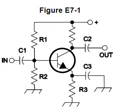
The type of circuit shown in Figure E7-1 is a common emitter amplifier. R1 and R2 bias the transistor. This type of bias is called voltage divider bias. R3 also sets the bias voltages for the transistor. The type of bias provided by R3 is called self bias.
QUESTION: What type of amplifier circuit is shown in Figure E7-1? (E7B12)
ANSWER: Common emitter
QUESTION: In Figure E7-1, what is the purpose of R1 and R2? (E7B10)
ANSWER: Voltage divider bias
QUESTION: In Figure E7-1, what is the purpose of R3? (E7B11)
ANSWER: Self bias
Another type of amplifier circuit is the emitter follower, or common collector amplifier. These types of amplifiers are often used as buffer amplifiers because they have low-impedance outputs that closely follow the base input voltage.
QUESTION: Which of the following describes an emitter follower (or common collector) amplifier? (E7B13)
ANSWER: An amplifier with a low impedance output that follows the base input voltage
Thermal runaway is one problem that can occur if a transistor amplifier is not designed correctly. What happens is that when the ambient temperature increases, the leakage current of the transistor increases, causing an increase in the collector-to-emitter current. This increases the power dissipation, further increasing the junction temperature, which increases yet again the leakage current. One way to prevent thermal runaway in a bipolar transistor amplifier is to use a resistor in series with the emitter. This resistor keeps the collector-to-emitter current under control.
QUESTION: What is one way to prevent thermal runaway in a bipolar transistor amplifier? (E7B15)
ANSWER: Use a resistor in series with the emitter
RF power amplifiers often generate unwanted signals via a process called intermodulation. Strong signals external to the transmitter combine with the signal being generated. These intermodulation products can cause the transmitter to output spurious signals. Odd-order, rather than even-order, intermodulation distortion products are of concern in linear power amplifiers because they are relatively close in frequency to the desired signal.
QUESTION: What is the effect of intermodulation products in a linear power amplifier? (E7B16)
ANSWER: Transmission of spurious signals
QUESTION: Why are odd-order rather than even-order intermodulation distortion products of concern in linear power amplifiers? (E7B17)
ANSWER: Because they are relatively close in frequency to the desired signal
One type of amplifier that is often used as a power amplifier is the grounded-grid amplifier. Grounded-grid amplifiers are relatively easy to build, are very stable in operation, and have a low input impedance. This is a useful characteristic because the output impedance of most amateur radio transmitters, which are used to drive these amplifiers, is 50 ohms.
QUESTION: What is a characteristic of a grounded-grid amplifier? (E7B18)
ANSWER: Low input impedance
Leave a Reply