
Linear power supplies are a type of power supply used in amateur radio stations. They are called linear power supplies because they use ICs called linear electronic voltage regulator to maintain a constant output voltage. The way they regulate the output voltage is to vary the conduction of current through a control element, usually a transistor. The circuit shown in Figure E7-2 below is a linear voltage regulator, and the control element is Q1. Q1, often called the pass transistor, controls the current supplied to the load, thereby keeping the output voltage constant even when the load varies. C2 bypasses rectifier output ripple around D1.
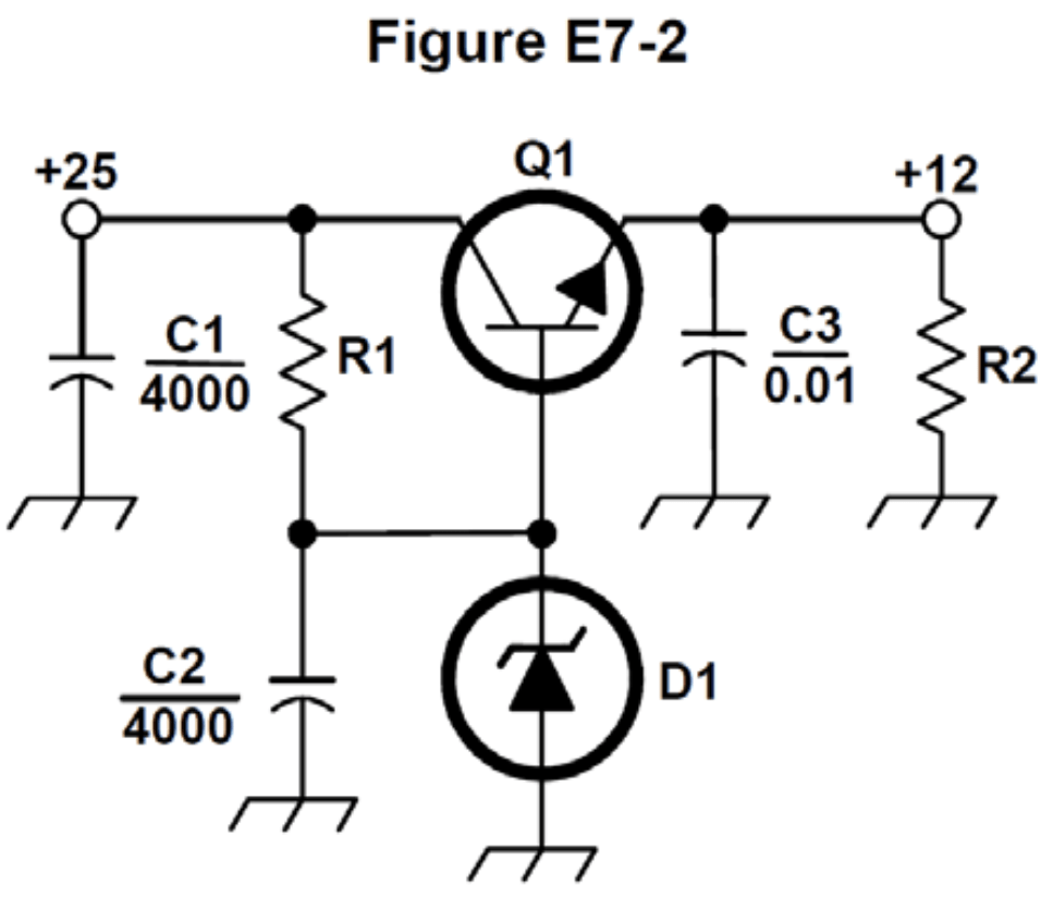
QUESTION: What type of circuit is shown in Figure E7-2? (E7D08)
ANSWER: Linear voltage regulator
QUESTION: How does a linear electronic voltage regulator work? (E7D01)
ANSWER: The conduction of a control element is varied to maintain a constant output voltage
QUESTION: What is the purpose of Q1 in the circuit shown in Figure E7-2? (E7D06)
ANSWER: It controls the current supplied to the load
QUESTION: What is the function of the pass transistor in a linear voltage regulator circuit? (E7D11)
ANSWER: Maintains nearly constant output voltage over a wide range of load current
QUESTION: What is the purpose of C2 in the circuit shown in Figure E7-2? (E7D07)
ANSWER: It bypasses rectifier output ripple around D1
Power supply designers typically use Zener diode as the voltage reference in a linear voltage regulator. D1 in Figure E7-2 is a zener diode.
QUESTION: What device is typically used as a stable voltage reference in a linear voltage regulator? (E7D03)
ANSWER: A Zener diode
There are two kinds of linear voltage regulators—the series regulator and the shunt regulator. A series regulator is the type of linear voltage regulator that usually makes the most efficient use of the primary power source. A shunt regulator is the type of linear voltage regulator that places a constant load on the unregulated voltage source.
QUESTION: Which of the following types of linear voltage regulator usually make the most efficient use of the primary power source? (E7D04)
ANSWER: A series regulator
QUESTION: Which of the following types of linear voltage regulator places a constant load on the unregulated voltage source? (E7D05)
ANSWER: A shunt regulator
An important analog voltage regulator specification is the drop-out voltage, which is the minimum input-to-output voltage required to maintain regulation. For example, if an analog voltage regulator has a drop-out voltage of 2 V, the input voltage must be at least 11 V in order to maintain an output voltage of 9 V.
QUESTION: What is the dropout voltage of an analog voltage regulator? (E7D12)
ANSWER: Minimum input-to-output voltage required to maintain regulation
Power dissipation is also important when designing a power supply with a series-connected linear voltage regulator. Excessive power dissipation reduces the efficiency of the supply and could require that you use large heat sinks to dissipate the power. The power dissipation by a series connected linear voltage regulator is the voltage difference from input to output multiplied by output current.
QUESTION: What is the equation for calculating power dissipated by a series linear voltage regulator? (E7D13)
ANSWER: Voltage difference from input to output multiplied by output current
Switching power supplies
Nowadays, you are as likely to find a switching power supply in an amateur radio station as you are a linear power supply. Switching power supplies use a much different method of regulating the output voltage than a linear supply. Instead of controlling the current through a control element, a switching supply varies the duty cycle of the control element to produce a constant average output voltage.
QUESTION: What is a characteristic of a switching electronic voltage regulator? (E7D02)
ANSWER: The controlled device’s duty cycle is changed to produce a constant average output voltage
Switching power supplies are usually less expensive and lighter than a linear power supply with the same output rating. Switching supplies are also generally more efficient than linear power supplies. The main reason that a high-frequency switching type high voltage power supply can be less expensive, lighter in weight, and more efficient than a linear power supply is that the high frequency inverter design uses much smaller transformers and filter components for an equivalent power output. Butt, this comes at a cost. Switching supply circuits are more complicated than the circuitry in a linear supply and may generate RF noise.
QUESTION: What is the primary reason that a high-frequency switching type high-voltage power supply can be both less expensive and lighter in weight than a conventional power supply? (E7D10)
ANSWER: The high frequency inverter design uses much smaller transformers and filter components for an equivalent power output
High-voltage power supplies
Most HF transceivers and VHF/UHF transceivers operate at a relatively low voltage. This is normally around 12 – 15 VDC. Some devices, such as older tube equipment and linear amplifiers need higher voltages to operate. These power supplies are quite different than the low-voltage linear and switching supplies describe above.
High-voltage supplies may also have a step-start circuit. The purpose of a “step-start” circuit in a high-voltage power supply is to allow the filter capacitors to charge gradually, thereby reducing the amount of current the supply draws when turned on.
QUESTION: What is the purpose of a step-start circuit in a high-voltage power supply? (E7D15)
ANSWER: To allow the filter capacitors to charge gradually
When several electrolytic filter capacitors are connected in series to increase the operating voltage of a power supply filter circuit, resistors should be connected across each capacitor. Doing this helps to equalize the voltage drop across each capacitor, discharge the capacitors when the supply is turned off, and provide a minimum load on the supply.
QUESTION: What is the purpose of connecting equal-value resistors across power supply filter capacitors connected in series? (E7D14)
ANSWER: All these choices are correct
- Equalize the voltage across each capacitor
- Discharge the capacitors when voltage is removed
- Provide a minimum load on the supply
Solar array charge controllers
Solar array charge controllers are voltage or current regulators that are used when charging batteries from a solar array. The main reason to use a charge controller with a solar power system is to prevent battery damage by overcharging them. Most solar panels that are rated at 12 V actually output 16 to 20 V, and if that output is not regulated, batteries connected to the solar panel may be damaged from overcharging.
QUESTION: What is the main reason to use a charge controller with a solar power system? (E7D09)
ANSWER: Prevention of battery damage due to overcharge
Leave a Reply