
The other day I worked Charlie, KM4ZZ. As I normally do, I loaded up his QRZ.Com page. What I found was this little gem: a description of the vertical, off-center-fed, half-wave dipole antenna that he uses for portable operations:
I use a variety of antenna systems. At home I have a 40M dipole up 35 feet. In the field I have horizontal dipoles, end fed verticals but usually I’m using an off center fed vertical half wave. I also use the 10 foot vertical whip on the PRC-104s on occasion.
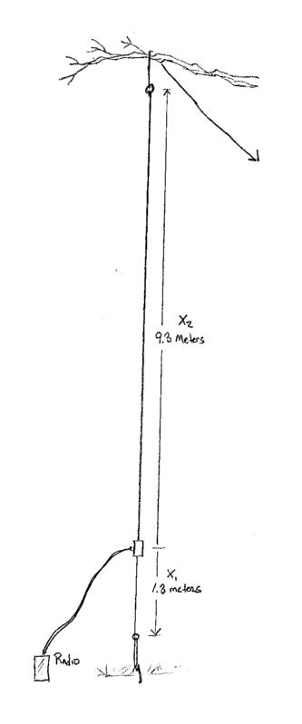
Amateur radio for me means operating portable. A high RF noise level in and around my house forces me into a nomadic existence. My first antenna was an inverted “V”, but setting that up in a public park was a real hassle. I was 30 plus feet under the feed point, but the guidelines were 60 plus feet out in two directions. This took up too much real estate in a place with kids, bikes, dogs and Frisbees all running around just looking for a way to stumble into a stake or guideline. I needed an antenna with a single support that minimized my footprint. I had great success with an end fed antenna following Steven Yates, AA5TB excellent web pages, but I wondered if I was losing some efficiency without a defined counterpoise. A center fed half wave would have the feed point too far off the ground, so the result is this: a VERTICAL, OFF CENTER FED HALF WAVE.
The feed point was chosen to give an impedance of 450 ohms. This would be only about 4 ½ feet off the ground and would allow a 9:1: Balan to be used to bring the impedance down to 50 ohms. Add in a 1:1 Balun to make the system a 9:1 Unun and the system is complete. The 9:1 Unun was designed with the assistance of Jerry Sevick’s excellent tests. This is a critical statement. Numerous eperiments with a 9:1 Balun failed until I realized I needed a 9:1 Unun!
I started with 18 gage automotive hookup wire, cut longer than the design lengths.
X=(150 Meters)/(frequency in MHz)
X1=0.131 X
X2= X-X1
X1 comes from the following equation that given us the feed point impedance of an off center fed half wave antenna.
Z=(72 Ohms)/(Sin(pi*X1/X)^2
Setting Z equal to 50 ohms and solving for X1 gives the correct feed point location
Using an antenna analyzer, I tuned the antenna by carefully shortening the lengths of the short and long arms until the resonate frequency was correct and the SWR was very close to 1:1. If you start with wires that are two long, it is important to remember that any cut on either arm raises the resonant frequency. A cut on the long arm also decrease the feed point impedance, and a cut on the short arm raises the feed point impedance. With these rules in mind I was able to achieve an SWR of 1.05 and a resonate frequency right in the middle of the SSB potion of the 20 Meter band. The whole band has an SWR of less than 1.3.
The antenna works very well. I use 15 feet of R-8X coax to hook up my trusty Yaesu FT-817. With five watts I get great reports from all over Europe and South America from Virginia. Because it is a half wave antenna, I don’t need any counterpoise which makes set up easy and minimizes the footprint.
When I asked for permission to publish this description, he stressed, “I think my description of the antenna is a bit incomplete without a more careful description of the 50:450 unun from Jerry Sevick’s book, Buildling and Using Baluns and Ununs. I found that only a Guanella type transformer works here, the Ruthroff type does not. ” If you don’t have the book, KH6GRT has a great post on his website on how to build one.
I think that this design is rather creative. It’s a resonant antenna, so it should be quite effiecient, and you don’t have to muck around with counterpoises. You could probably even make a fan version of this for multi-band operation, or simply have a set of elements for each of the different bands that you want to operate.
Hey Dan,
Thanks for the very interesting link! I’m doing something similar with my end-fed half-wave (see my video of a portable op here: https://www.youtube.com/watch?v=GCzBHOSpHSE), though now that I see this, KM4ZZ’s solution might be even better for my purposes. Thanks again and 73s, Lucien
Fascinating article, but let me say that the grey quoted text is very hard to read. Just so you know.
Ed KC8SBV
Just ran across this searching for vertical dipole ideas. It is a good idea, thanks for posting,
But KM4ZZ clearly states he prefers an unun but all I found by searching for KH6GRT was his (excellent) article on a balun at http://www.qsl.net/kh6grt/page4/balun/balun.htm. Please post where you found an unun from KH6GRT.
Interesting indeed but as a beginner I have a hard time getting my head around this:
“9:1: Balan to be used to bring the impedance down to 50 ohms. Add in a 1:1 Balun to make the system a 9:1 Unun and the system is complete. ”
Does that mean I need a Guanella balun described on the KH6GRT website and an additional 1:1 Balun and how does that make a 9:1 unun?
Your description “9:1: Balan to be used to bring the impedance down to 50 ohms. Add in a 1:1 Balun to make the system a 9:1 Unun and the system is complete. ” Is confusing to many newbies.
My understanding is that the antenna is an unbalanced antenna with around 450 ohm feed impedance and the 9:1 UNUN matches the 450 ohm unbalanced to 50 ohm unbalanced (for the coax feed)?
If the output 9:1 is unbalanced (unun), can you please explain why a 1:1 BAL-UN is used after the 9:1 UNUN? Would a 9:1 UNUN followed by a 1:1 choke work? A sketch to the article as to what the arrangement might be, will probably help many.
Yes I think he´s referring to a RF choke after the 9:1 un-un. The same configuration is used in end-fed antennas.
Okay, so I modeled this antenna and found it to be a regular end fed half wave vertical with the bottom acting as a short counterpoise of sorts. The elevation angle is 16 degrees, making it a decent DX antenna. The gain predicted is .67 dBi
Modeled exactly as in the article, the feed impedance is 655 ohms and slightly inductive. If the bottom wire is pulled horizontal (like a regular radial) the impedance shifts to 550 ohm capacitive, with nothing changing as regards angle and gain.
I also fed the original antenna at the bottom, like a conventional end fed wire of 10.6m and found the predicted impedance to be 955 oms capacitive. It must be emphasized that the feed impedance of such an antenna will vary with the height above ground. .
The only difference I notice is that the recommended feed point would make the impedance a better match with a 9:1 than if one would use it as a conventional 1/2 wave end fed vertical.
Since modelling, I have built this antenna as in the original article above and with the different feed methods stated above. As expected, matching was not as straight forward as in the models, but that is always expected with the reactances and heights and surrounds in the real world. I have worked some good DX with it. as I used to do with my end fed half wave.
First, this antenna does not clarify the operating frequency range of the antenna;
Second, I don’t understand that the antenna to the ground is 1:9 unun and 1:50unun;
Third, if it’s EFHW, 20-10m, isn’t it good to use 1:49un;
Is the grounding grid (grounding) still needed;
Hi Dan,
Your formula for X has me curious as to where the value of 150 meters came from. What am I missing here. Looking forward to getting this project completed. Radials have always been a challenge. Thank you for the info.
73,
John McMahan
WP3ZP
Hi, John…Since wavelength(m) = 300/f(MHz), a half-wave would be 150/f(MHz). Since the rule of thumb for the length of dipoles in feet is 468/f(MHz), perhaps that would get one a little closer on the first go-round.
Now that you’ve re-kindled my interest in this topic, I’m thinking that it might be interesting to make a 10m or 6m version of this antenna.
Let me know how your attempt turns out.