
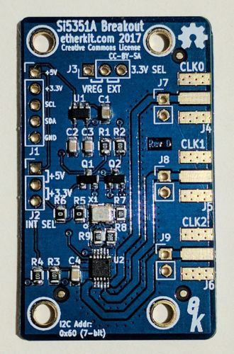
 For my next trick, I’m working on a sample chapter of a book I’m calling Ham Radio for Hackers. I’ve written about this before, but now I’m getting serious about it—well, at least as serious as I get about anything. The first chapter is going to describe a simple signal source that uses an Arduino and the Etherkit Si5351 Breakout Board (see right).
I had actually purchased one of these boards a couple of years ago, when Jason, NT7S, first started selling them. Back then, he was offering them as kits. (Now, he sells them as assembled and calibrated units for only $10.)
This post isn’t about the book, but rather building this kit. As you can see from the photo, this board is all surface-mount. I put this off for two years because, frankly, I was a little scared of working with such small parts. I had actually built a couple of other small kits that used surface mount components, including a dummy load from Third Planet Solar, but those part were a lot bigger than the ones on this board.
I’m happy to report that, after all that angst about working with such small components, I managed to get all 17 surface-mount components on the board without losing a single one. Not only that, but the board works great!
Here are some of the keys to my success:
- I used a very fine point tip on my soldering iron: the Weller PTS7.
- I used solder with a diameter of only .015-in. This helped me control how much solder I used on each joint.
- I used some tweezers that I purchased a couple of years ago at a hamfest, when I was considering doing surface-mount construction. Currently, I have only one pair of straight tweezers, but I think having a pair of angled tweezers would make placing and holding components in place easier in some cases.
- I have a pair of high-magnification reading glasses that help me see the tiny components.
I was really concerned about soldering the Si5351 chip. The lead pitch is only 0.5 mm, making it almost impossible to not bridge the pins. NT7S’s solution was to be as careful as you could when soldering this chip, but then use solder braid to eliminate any solder bridging. That seemed to do the job.
I’m really geeked about this, and after I finish the book, I’ll be ready for my next challenge. Please tell me about your experiences with surface-mount components. Also, please share your tips for building circuits with them.
I also use a PTS7 tip bent at an angle; you can squeeze it in to touch both sides of a cap/resistor/jumper so that you can move or remove the part. I’ve used it for a number of 144-pin QFPs successfully.
Likewise, I also use a roll of Kester 63/37 flux core 0.15” solder.
Don’t try it without a temperature controlled iron (a simple one will do fine).
A well lit desk magnifier is a must.
You’ll end up with lots of different tweezers eventually.
Something to hold small workpieces steady helps.
One critical point: Flux is your friend; the amount of flux in the solder wire itself isn’t enough for SMT work. It’s generally adequate for through-hole, but SMT requires it to clean much more surface area. I use a Kester 186 flux pen for most things, and it seems gets the job done.
The practical minimum size for hand assembly of SMT passives is about 0603. Now that I’ve done several, I think I can manage smaller, but it’s very tricky, and a packed PCB can be a big challenge (order of assembly becomes critical).
Leadless chip carriers are probably the hardest parts I’ve encountered.
BGAs aren’t possible with these methods. Controlled temperature hot plates are probably the only way to so this (and I haven’t tried it myself yet).
If you’re comfortable with through-hole, and you have some patience, SMT isn’t as bad as you might expect. Don’t try one as a first project, though.
In my mind, and it changed recently, I built a DC rx with a VFO, it separated active elements from the passives, to keep heat out, and used lots of small NP0 caps to distribute the RF currents, minimizing their heating. It wasn’t difficult, and amazingly drifts so little, i say it’s a great learning experience