
Many amateurs use directional antennas because they are said to have “gain.” When this term is used, what it means is that a directional antenna will output more power in a particular direction than an antenna that is not directional. This only makes sense; You can’t get more power out of an antenna than you put in. Assuming each is driven by the same amount of power, the total amount of radiation emitted by a directional gain antenna is the same as the total amount of radiation emitted from an isotropic antenna.
QUESTION: How does the total amount of radiation emitted by a directional gain antenna compare with the total amount of radiation emitted from a theoretical isotropic antenna, assuming each is driven by the same amount of power? (E9B07)
ANSWER: They are the same
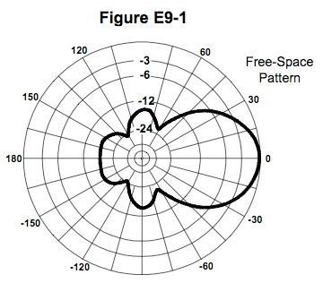
To evaluate the performance of directional antennas, manufacturers will measure the field strength at various points in a circle around the antenna and plot those field strengths, creating a chart called the azimuth antenna radiation pattern. Figure E9-1 is a typical azimuth antenna radiation pattern.
The antenna radiation pattern shows the relative strength of the signal generated by an antenna in its “far field.” The far-field of an antenna is the region where the shape of the antenna pattern is independent of distance.
QUESTION: What is the far field of an antenna? (E9B08)
ANSWER: The region where the shape of the antenna pattern is independent of distance
From the antenna radiation pattern, we can tell a bunch of things about the antenna. One of them is beamwidth. Beamwidth is a measure of the width of the main lobe of the radiation pattern. To determine the approximate beamwidth in a given plane of a directional antenna, find the two points where the signal strength of the antenna is 3 dB less than maximum and determine the angle between them. In the antenna radiation pattern shown in Figure E9-1, the 3-dB beamwidth is 50 degrees.
QUESTION: In the antenna radiation pattern shown in Figure E9-1, what is the beamwidth? (E9B01)
ANSWER: 50 degrees
Another parameter that’s important for a directional antenna is the front-to-back ratio. The front-to-back ratio is a measure of how directional an antenna is. The higher this ratio, the more directional the antenna. When the radiation pattern is set up so that the forward lobe has a value of 0, as it is in Figure E9-1, the front-to-back ratio is the maximum value of the rear lobe. In the antenna radiation pattern shown in Figure E9-1, the front-to-back ratio is 18 dB.
QUESTION: In the antenna radiation pattern shown in Figure E9-1, what is the front-to-back ratio? (E9B02)
ANSWER: 18 dB
A similar parameter is the front-to-side ratio. In the antenna radiation pattern shown in Figure E9-1, the front-to-side ratio is 14 dB.
QUESTION: In the antenna radiation pattern shown in Figure E9-1, what is the front-to-side ratio? (E9B03)
ANSWER: 14 dB
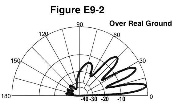
Because antennas radiate in three dimensions, the azimuth antenna pattern tells only part of the story. To get a complete picture of antenna performance, you also want to know what the antenna pattern is in the vertical direction. This type of pattern is called the elevation antenna pattern, and is shown in Figure E9-2. This elevation pattern shows four lobes in the forward direction, and the largest, or the lobe with the peak response, has an elevation angle of 7.5 degrees.
QUESTION: What type of antenna pattern is shown in Figure E9-2? (E9B05)
ANSWER: Elevation
QUESTION: What is the elevation angle of peak response in the antenna radiation pattern shown in Figure E9-2? (E9B06)
ANSWER: 7.5 degrees
QUESTION: What is the front-to-back ratio of the radiation pattern shown in Figure E9-2? (E9B04)
ANSWER: 28 dB
Antenna design
To help design antennas, many amateurs use antenna modeling programs. Antenna modeling programs can provide the following information:
- SWR vs. frequency charts
- Polar plots of the far-field elevation and azimuth patterns
- Antenna gain
The type of computer program technique commonly used for modeling antennas is method of moments. Programs that use the method of moments analysis technique model a wire as a series of segments, each having a uniform value of current.
QUESTION: What type of computer program technique is commonly used for modeling antennas? (E9B09)
ANSWER: Method of Moments
QUESTION: What is the principle of a Method of Moments analysis? (E9B10)
ANSWER: A wire is modeled as a series of segments, each having a uniform value of current
The more segments your simulation uses, the more accurate the results. The problem with using too many segments, though, is that the program will take a very long time to run. You don’t want to use too few segments, though. Decreasing the number of wire segments in an antenna model below the guideline of 10 segments per half-wavelength may cause the computed feed point impedance to be incorrect.
QUESTION: What is a disadvantage of decreasing the number of wire segments in an antenna model below 10 segments per half-wavelength? (E9B11)
ANSWER: The computed feed point impedance may be incorrect