
On the amateur radio subreddit, some guy posted a link to his ePay store where he’s selling fancy crystal radios. Since there’s a rule that you can’t post ads, his post was quickly removed, but not before I clicked on a link and got a look at his work. Honestly, some of it looked pretty interesting, but there was one thing he was selling that I questioned.
One of his products is a little board with four germanium diodes in parallel (see below). I’m going to guess that these are 1N34A diodes. When I asked him what the purpose was for connecting four diodes in parallel like that, he replied, “To decrease the Diode Resistance so it improves the Diode performance in a Crystal Radio (his caps, not mine).”
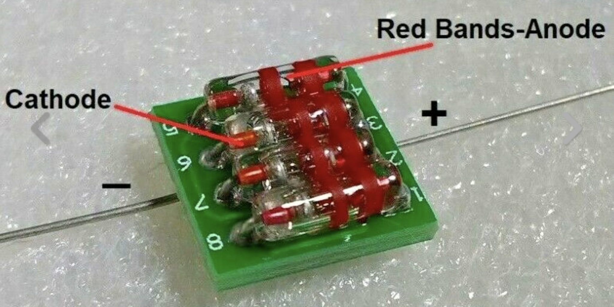
Now, it’s true that connecting resistors in parallel will decrease the total resistance, but let’s look at a typical crystal radio circuit:
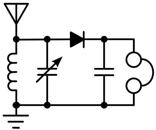
This circuit uses high-impedance headphones or a high-impedance earphone because there is no powered amplifier. The only power comes from the received radio wave itself. This means that very little current will be flowing in the circuit, so there’s really not much to gain by decreasing the “Diode Resistance.”
So, to answer my own question, no, I don’t think that paralleling diodes in a crystal radio circuit would make it work noticeably better.
I’ve seen it talked about before on some of the crystal radio sites. You can find some stuff about it in the “Diodes” section here: http://www.crystal-radio.eu/ I haven’t messed with crystal radios (yet) so I can’t really say how much of a difference it makes. I’d be willing to guess that it may make a difference given the very low currents they are working with. Sounds like something fun to try.
Only one diode will conduct, the one with the lowest Vforward. Rather than binning the diodes, perhaps putting four of them in parallel and letting the current select the lowest Vforward diode provides some small benefit, particularly if you don’t know or trust your source of diodes.
My guess is that temperature will have a bigger difference in Vforward than part to part variation from the same batch. I’ve heard, however, that germanium radios sound better in winter than summer – but that could be attributed to ionispheric changes rather than whether the diode itself has changed due to temperature.
That said, it feels more like snake oil.
Would itt not be an advantage to add a tiny bias voltage to the diode to lower its conduction break over voltage?
I haven’t messed with a crystal set in perhaps 60 years or so, but that just came to mind reading this thread…
A testing tip. So how to check diode vs. diode or four diodes against one diode or other various detectors? Well, you can swap them in and out of a circuit but if the results are not very pronounced it is difficult to tell. When receiving a station, the signal may fade or rise before you can substitute the crystals. Recalling which is working better is not easy with such a small output. You can meter the signal but the program you are listening to may have various audio outputs and as mentioned the signal can shift. I built a small board that seats different diodes and switches between them as rapidly as my fingers can do it. I have discovered that when I purchased a number of diodes that I sadly had to toss out the majority of them because of poor performance when checked by my switching device. It didn’t matter as to how much I spent for the diodes-you don’t always get what you pay for. Harry N9CQX
I tried paralleling two diodes in my crystal radio and sound definitely got louder. I quickly switched the second diode in and out and the difference was apparent. Note that my design is broadband/without tuner – I don’t know whether that should affect things though.
The diode in a crystal set is operating below the knee. So the resistance is still high when conducting. The reason for h-Z ‘phones is to utilise the current being passed y the diode. A second diode will reduce the forward resistance, so we should get twice the current, giving 6dB or 1 S-unit increase. Dave G3PVH