
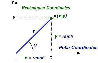
Most often when we plot values on a graph, we use the rectangular, or Cartesian, coordinate system. The two numbers that are used to define a point on a graph using rectangular coordinates are the coordinate values along the horizontal and vertical axes. (E5C11) In the graph above, point P is at x,y. Rectangular coordinates are often used to display the resistive, inductive, and/or capacitive reactance components of an impedance. (E5C13)
When thinking about how capacitive reactances, inductive reactances, and resistance combine, it’s useful to think in terms of polar coordinates. Polar coordinates are often used to display the phase angle of a circuit containing resistance, inductive and/or capacitive reactance. (E5C14) In a polar-coordinate system, each point on the graph has two values, a magnitude (shown by r in the figure above) and an angle (shown by θ in the figure above).
When using rectangular coordinates to graph the impedance of a circuit, the vertical axis represents the reactive component. (E5C10) To figure out the impedance of a circuit, you first plot the inductive reactance on the positive y-axis and the capacitive reactance on the negative y-axis. The net reactance, X, will be the sum of the two reactances.
When using rectangular coordinates to graph the impedance of a circuit, the horizontal axis represents the resistive component. (E5C09) After you’ve computed the net reactance, you plot the resistance on the x-axis and compute the magnitude of the impedance, shown by r in the graph above. If you consider that r is the third side of a right triangle made up of the sides r, x, and y, r is equal to the square root of x2 and y2.
Let’s take a look at an example. In polar coordinates, is the impedance of a network consisting of a 100-ohm-reactance inductor in series with a 100-ohm resistor is 141 ohms at an angle of 45 degrees. (E5C01) In this example, x=100 and y=100, so
r = sqrt (X2 + R2) = sqrt (1002 + 1002) = sqrt (20000) = 141 ohms.
The cosine of the phase angle θ is equal to x/r, or 100/141, or .707. If you look up this value in a table of cosines, you’ll find that the angle is 45 degrees.
Here’s another thing to notice. When the value of the reactance is equal to the value of the resistance, the angle will be either 45 degrees or -45 degrees, depending on whether the net reactance is inductive or capacitive.
Now, let’s look at an example with both inductive and capacitive reactance. In polar coordinates, the impedance of a network consisting of a 100-ohm-reactance inductor, a 100-ohm-reactance capacitor, and a 100-ohm resistor, all connected in series is 100 ohms at an angle of 0 degrees. (E5C02) In this case, the inductive reactance and the capacitive reactance are the same, meaning that there is no net reactance. If you plot the impedance of a circuit using the rectangular coordinate system and find the impedance point falls on the right side of the graph on the horizontal axis, you know that the circuit impedance is equivalent to a pure resistance. (E5C12)
Here’s an example with unequal inductive and capacitive reactances. In polar coordinates, the impedance of a network consisting of a 300-ohm-reactance capacitor, a 600-ohm-reactance inductor, and a 400-ohm resistor, all connected in series is 500 ohms at an angle of 37 degrees. (E5C03) Here’s how we got that result:
X = 600 – 300 = 300 ohms
r = sqrt (X2 + R2) = sqrt (3002 + 4002) = sqrt (250000) = 500 ohms
θ = cos-1(x/r) = cos-1(400/500) = 37 degrees
Here are some more examples. I’ll leave the solutions up to you:
- In polar coordinates, the impedance of a network consisting of a 400-ohm-reactance capacitor in series with a 300-ohm resistor is 500 ohms at an angle of -53.1 degrees. (E5C04)
- In polar coordinates, the impedance of a network consisting of a 400-ohm-reactance inductor in parallel with a 300-ohm resistor is 240 ohms at an angle of 36.9 degrees. (E5C05)
- In polar coordinates, the impedance of a network consisting of a 100-ohm-reactance capacitor in series with a 100-ohm resistor is 141 ohms at an angle of -45 degrees. (E5C06)
- In polar coordinates, the impedance of a network comprised of a 100-ohm-reactance capacitor in parallel with a 100-ohm resistor is 71 ohms at an angle of -45 degrees. (E5C07)
- In polar coordinates, what is the impedance of a network comprised of a 300-ohm-reactance inductor in series with a 400-ohm resistor is 500 ohms at an angle of 53 degrees. (E5C08)
- In polar coordinates, the impedance of a series circuit consisting of a resistance of 4 ohms, an inductive reactance of 4 ohms, and a capacitive reactance of 1 ohm is 5 ohms at an angle of 37 degrees. (E5C18)
In polar coordinates, how do you calculate the impedance of a network comprised of a 400 ohm inductive reactance in parallel with a 300 ohm resistor.
The impedance is:
Z = XL*R / sqrt(XL**2 + R**2) = 400*300/sqrt(160000+90000) = 120000/500 = 240 ohms
The phase angle is the inverse tangent of R/XL = inv tan (300/400) = 37 deg, and because this is an inductive reactance it’s a positive angle or +37 deg.
Dan: thanks for filling in some of my education gaps on rf circuit design.
Dave, WA2BXY
After some gear-grinding in my brain, this finally clicked – thanks for making it fairly easy to understand! Sure to help with the Extra exam. Cheers!
-tyler KN6CMK
My pleasure, Tyler. I love comments like this!