
As of July 1, 2020, this post will be obsolete. See the corresponding post from my 2020 version of No Nonsense Extra Class License Study Guide.
When you put a voltage across a capacitor, current will flow into the capacitor and the voltage across the capacitor will increase until the voltage across it reaches the value of the supply voltage. This is not a linear function. By that I mean that the voltage will increase quite rapidly at first, but the rate of increase will slow as time goes on.
To see how this works, let’s consider the RC time constant. The time constant of an RC circuit is equal to the resistance in the circuit times the capacitance, or simply R x C. For example, the time constant of a circuit having two 220-microfarad capacitors and two 1-megohm resistors, all in parallel is 220 seconds. (E5B04)
The equivalent resistance of two 1 MΩ resistors in parallel is 500 kΩ. The equivalent capacitance of two 220 μF capacitors in parallel is 440 μF. The time constant is RxC = 440 x 10-6 x 500 x 103 = 220 s.
One time constant is the term for the time required for the capacitor in an RC circuit to be charged to 63.2% of the applied voltage. (E5B01) Similarly, one time constant is the term for the time it takes for a charged capacitor in an RC circuit to discharge to 36.8% of its initial voltage. (E5B02)
A capacitor charges to 86.5% of the applied voltage, or discharges to 13.5% of the starting voltgage, after two time constants. After three time constants, a capacitor is charged up to 95% of the applied voltage or discharged to 5% of the starting voltage.
Phase relationships
In an AC circuit, with only resistors, the voltage and current are in phase. What that means is that the voltage and current change in lock step. When the voltage increases, the current increases. When the voltage decreases, the current decreases.
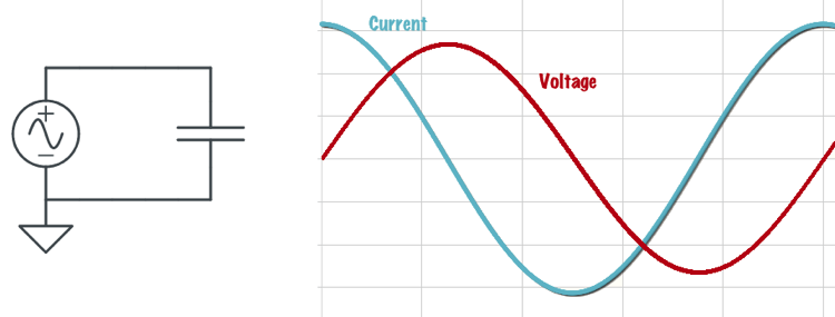
When there are capacitors and inductors in an AC circuit, however, the phase relationship between the voltage and current changes. Specifically, the relationship between the current through a capacitor and the voltage across a capacitor is that the current leads voltage by 90 degrees. (E5B09) We could also say that the voltage lags the current by 90 degrees. See figure below.
What that means is that the current through a capacitor increases and decreases before the voltage across a capacitor increases and decreases. We say that the current leads the voltage by 90 degrees because it starts increasing one-quarter of a cycle before the voltage starts increasing.
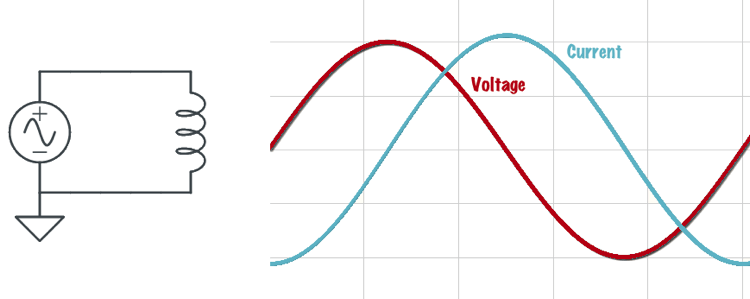
The relationship between the current through an inductor and the voltage across an inductor is that the voltage leads current by 90 degrees. (E5B10) We could also say that the current lags the voltage. See figure below.
What that means is that the voltage across an inductor increases and decreases before the current through the inductor increases and decreases. We say that the voltage leads the voltage by 90 degrees because it starts increasing one-quarter of a cycle before the current starts increasing.
When there are resistors as well as a capacitor or inductor or both in a circuit, the relationship is a little more complicated. Let’s look at what happens in the series RLC circuit shown below.
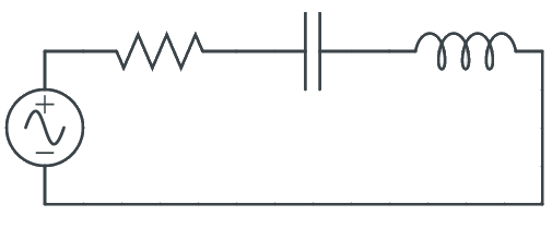
In this circuit, there is resistance, capacitive reactance, and inductive reactance. The reactances subtract from one another. If the capacitive reactance is greater than the inductive reactance, the net reactance will be capacitive. If the inductive reactance is greater than the capacitive reactance, the net reactance will be inductive.
The resistance and the reactance add to one another, but they add vectorially. The reason for this is that the reactance will be 90 degrees out of phase with the resistance. This is shown in the figure below.
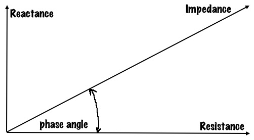
The magnitude of the impedance, Z, will be equal to √(R2 + X2) and the tangent of the phase angle will be equal to X/R. Let’s see how this works in several examples.
If XC is 500 ohms, R is 1 kilohm, and XL is 250 ohms, the phase angle between the voltage across and the current through the series RLC circuit is 14.0 degrees with the voltage lagging the current. (E5B07) Here’s how to calculate that:
X = XC – XL = 250 Ω (capacitive)
phase angle = tan-1 (250/1000) = 14 degrees.
and because the reactance is capacitive, the voltage will lag the current.
If XC is 100 ohms, R is 100 ohms, and XL is 75 ohms, the phase angle between the voltage across and the current through the series RLC circuit is 14 degrees with the voltage lagging the current. (E5B08) Here’s the calculation:
X = XC – XL = 25 Ω (capacitive)
phase angle = tan-1 (25/100) = 14 degrees.
and because the reactance is capacitive, the voltage lags the current.
If XC is 25 ohms, R is 100 ohms, and XL is 50 ohms, the phase angle between the voltage across and the current through the series RLC circuit is 14 degrees with the voltage leading the current. (E5B11) Here’s the calculation:
X = XL – XC = 25 Ω (inductive)
phase angle = tan-1 (25/100) = 14 degrees.
and because the reactance is inductive, the voltage leads the current.
Susceptance and admittance
While we most often work with reactances and impedances in amateur radio, in some cases, it’s more advantageous to work with susceptance and admittance.
Susceptance is the inverse of reactance.(E5B06) The unit of susceptance is the siemens (S). B is the letter is commonly used to represent susceptance. (E5B13) In mathematical terms,
B = 1/X
When the magnitude of a reactance is converted to a susceptance, the magnitude of the susceptance is the reciprocal of the magnitude of the reactance. (E5B05) When the phase angle of a reactance is converted to a susceptance, the sign is reversed. (E5B03)
Admittance is the inverse of impedance. (E5B12) The unit of admittance is the siemens, and like impedance, is a complex quantity.
Leave a Reply