
As always, comments are appreciated. I especially had some trouble distilling the explanation of questions on software-defined radio. There were three questions added on this topic to the question pool…..Dan
Power supplies; schematic symbols
Power supplies are devices that convert AC power to the DC voltages needed to power amateur radio equipment. There are two main types of power supplies available: linear power supplies and switching power supplies.
Linear supplies use a transformer to transform the voltage up or down, a rectifier to convert the AC voltage to a DC voltage, and capacitors and inductors to smooth the output voltage. The rectifier in a linear supply may be a half-wave rectifier, a full-wave rectifier, or a bridge rectifier.
As the name implies a half-wave rectifier converts half, or 180 degrees, of an AC cycle to DC, while a full-wave rectifier converts all 360 degrees of the cycle to AC. The bridge rectifier also converts the complete cycle to DC.
QUESTION: What portion of the AC cycle is converted to DC by a half-wave rectifier? (G7A05)
ANSWER: 180 degrees
QUESTION: What portion of the AC cycle is converted to DC by a full-wave rectifier? (G7A06)
ANSWER: 360 degrees
Each type of rectifier has its advantages and disadvantages. A half-wave rectifier uses only a single diode, but only converts half the AC power available into DC. A full-wave rectifier converts the entire AC power available into DC, but requires a center-tapped transformer. A bridge rectifier does not require the use of a more expensive center-tapped transformer, but needs four diodes.
QUESTION: What is an advantage of a half-wave rectifier in a power supply? (G7A04)
ANSWER: Only one diode is required
QUESTION: Which type of rectifier circuit uses two diodes and a center-tapped transformer? (G7A03)
ANSWER: Full-wave
The output of an unfiltered rectifier circuit is a series of DC pulses. For the half-wave rectifier, the frequency of the pulses is the same as the AC input, as there is an output only when the AC input goes positive. For the full-wave rectifier, the output frequency is twice that, as it outputs a pulse when the AC goes positive and negative.
QUESTION: What is the output waveform of an unfiltered full-wave rectifier connected to a resistive load? (G7A07)
ANSWER: A series of DC pulses at twice the frequency of the AC input
The output of a rectifier connects to a filter made up of capacitors and inductors. The purpose of this filter is to filter out the AC component of the pulsed DC and output a steady DC voltage.
QUESTION: Which of the following components are used in a power supply filter network? (G7A02)
ANSWER: Capacitors and inductors
A component often found across the output of a power supply is a power-supply bleeder resistor. The purpose of this resistor is to discharge, or bleed off, the charge on the filter capacitors when the power supply is turned off. The value of this resistor is normally a very high value so that very little current flow through it during normal operation.
QUESTION: What useful feature does a power supply bleeder resistor provide? (G7A01)
ANSWER: It ensures that the filter capacitors are discharged when power is removed
Switching, or switched-mode power supplies are now being sold by many vendors. Switching supplies are smaller and lighter than linear supplies, but the circuits are much more complex than linear power supply circuits.
QUESTION: Which of the following is an advantage of a switchmode power supply as compared to a linear power supply? (G7A08)
ANSWER: High frequency operation allows the use of smaller components
When designing or troubleshooting radios, amateur radio operators use schematic diagrams to describe circuits. Various symbols represent the different types of components. A typical schematic is shown in Figure G7-1.
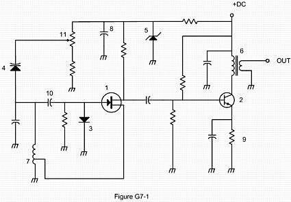
QUESTION: Which symbol in figure G7-1 represents a field effect transistor? (G7A09)
ANSWER: Symbol 1
QUESTION: Which symbol in figure G7-1 represents a Zener diode? (G7A10)
ANSWER: Symbol 5
QUESTION: Which symbol in figure G7-1 represents an NPN junction transistor? (G7A11)
ANSWER: Symbol 2
QUESTION: Which symbol in Figure G7-1 represents a solid core transformer? (G7A12)
ANSWER: Symbol 6
QUESTION: Which symbol in Figure G7-1 represents a tapped inductor? (G7A13)
ANSWER: Symbol 7
Digital circuits
Digital circuits are circuits whose output are one of two voltages—either “on” or “off,” “high” or “low,” “one” or “zero.” Digital circuits use the binary system to represent numbers because each of the digits in a binary number is either a 1 or a 0.
We use digital circuits to implement logic functions, and we call a circuit that implements a logic function a “gate.” Two typical logic functions are AND and NOR. The output of an AND gate is 1 when all of the inputs are 1. The output of a NOR gate is 1 only when both inputs are 0.
QUESTION: Which of the following describes the function of a two-input AND gate? (G7B03)
ANSWER: Output is high only when both inputs are high
QUESTION: Which of the following describes the function of a two input NOR gate? (G7B04)
ANSWER: Output is low when either or both inputs are high
Integrated circuits that provide more complex logic functions, such as flip-flops, counters and shift registers, are also available. As the name implies, a counter counts input pulses and outputs the count in binary. The figure below shows a three-bit counter made with 3 D flip-flops. A D flip-flop is a circuit whose output, Q, changes when it receives a clock pulse. After the clock pulse, Q is equal to D. The other output, Q[bar] is the inverse of Q.
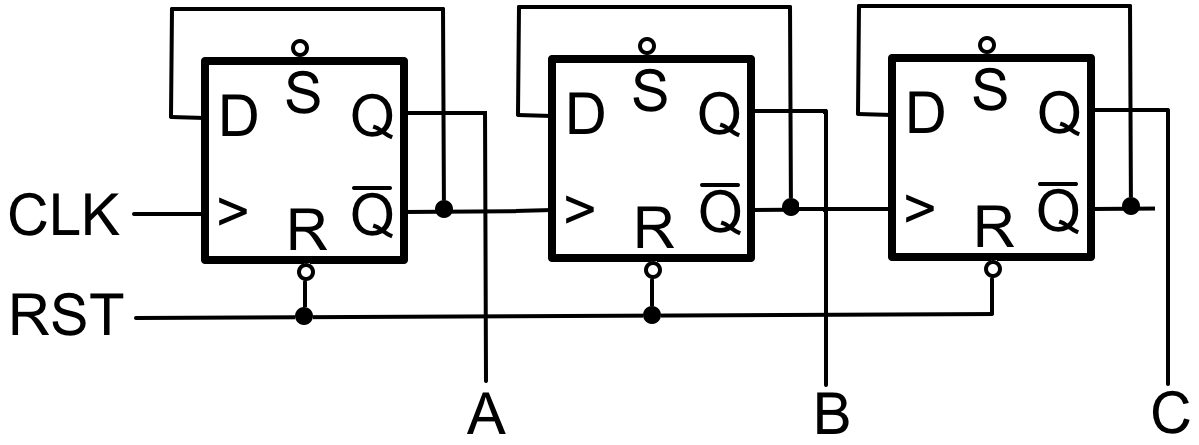
A three-bit counter has eight output states.
QUESTION: How many states does a 3-bit binary counter have? (G7B05)
ANSWER: 8
A shift register consists of an array of flip flops whose outputs are connected to the input of the next flip-flop in the chain. When the shift register receives a clock pulse, data is shifted down the array.
QUESTION: What is a shift register? (G7B06)
ANSWER: A clocked array of circuits that passes data in steps along the array
Oscillators and amplifiers
An oscillator is a circuit that generates an AC output signal. It normally consists of an amplifier, part of whose output is fed back to the input through a filter. This feedback keeps the circuit oscillating, while the filter determines the frequency of the oscillation.
QUESTION: Which of the following are basic components of a sine wave oscillator? (G7B07)
ANSWER: A filter and an amplifier operating in a feedback loop
An “LC” oscillator uses an inductor and a capacitor connected so that they form what’s called a tank circuit to provide feedback. The tank circuit is the filter that determines the frequency of oscillation.
QUESTION: What determines the frequency of an LC oscillator? (G7B09)
ANSWER: The inductance and capacitance in the tank circuit
There are many different types of amplifiers. These types are often categorized by class: Class A, Class B, Class C, and Class D amplifiers. Each class of amplifiers has certain characteristics. Linear amplifiers, for example, are usually Class A amplifiers. Class A amplifiers add very little distortion and the output waveform is very close to the input waveform, just larger. This makes them the best choice for amplifying AM and SSB phone signals.
QUESTION: Which of the following describes a linear amplifier? (G7B10)
ANSWER: An amplifier in which the output preserves the input waveform
The Class C amplifier, on the other hand, is not linear. Fortunately, an amplifier need not be linear to amplify FM and CW signals. They are a good choice for FM and CW because they are more efficient than Class A, Class B, and Class AB amplifiers.
QUESTION: Which of these classes of amplifiers has the highest efficiency? (G7B02)
ANSWER: Class C
QUESTION: For which of the following modes is a Class C power stage appropriate for amplifying a modulated signal? (G7B11)
ANSWER: FM
QUESTION: How is the efficiency of an RF power amplifier determined? (G7B08)
ANSWER: Divide the RF output power by the DC input power
High-power amplifiers are often prone to self-oscillation due to stray capacitive feedback. To prevent this from happening, you induce some feedback that is out of phase with the stray capacitive feedback to neutralize it.
QUESTION: What is the reason for neutralizing the final amplifier stage of a transmitter? (G7B01)
ANSWER: To eliminate self-oscillations
Receivers and transmitters, filters, oscillators
Filters are very important circuits in amateur radio equipment. As the name implies, these circuits are used to clarify or process radio signals. For example, one type of filter—a low-pass filter—passes all signals whose frequencies are below a certain frequency, called the “cutoff frequency.”
QUESTION: What is the frequency above which a low-pass filter’s output power is less than half the input power? (G7C12)
ANSWER: Cutoff frequency
One application of a low-pass filter is to block the VHF and UHF harmonics produced by an amateur transceiver from reaching the antenna. To do this, you would connect the input of the filter to the output of your transceiver and the output of the filter to your antenna system.
QUESTION: What should be the impedance of a low-pass filter as compared to the impedance of the transmission line into which it is inserted? (G7C06)
ANSWER: About the same
Band-pass filters are designed to pass signals between two frequencies—called the passband—while rejecting signals outside this range. The width of this frequency range is the difference between the two frequencies at which the signal power is one-half the maximum power. The difference between the upper and lower half-power frequencies is called the bandwidth of the filter.
QUESTION: The bandwidth of a band-pass filter is measured between what two frequencies? (G7C14)
ANSWER: Upper and lower half-power
How well a filter rejects signals outside the passband is called ultimate rejection.
QUESTION: What term specifies a filter’s maximum ability to reject signals outside its passband? (G7C13)
ANSWER: Ultimate rejection
Of course, filters aren’t perfect. They will reduce, or attenuate, the input signal level of the input signal, by some amount, even if the signal is within the passband.
QUESTION: What term specifies a filter’s attenuation inside its passband? (G7C15)
ANSWER: Insertion loss
Filters are also used in amateur radio transmitters. For example, to produce a single sideband signal, you combine the audio signal and the signal from the carrier oscillator in a balanced modulator. The output of the balanced modulator includes both the upper and lower sidebands. To obtain a single sideband, you filter out the sideband you don’t want.
QUESTION: Which circuit is used to combine signals from the carrier oscillator and speech amplifier then send the result to the filter in some single sideband phone transmitters? (G7C02)
ANSWER: Balanced modulator
QUESTION: Which of the following is used to process signals from the balanced modulator then send them to the mixer in some single sideband phone transmitters? (G7C01)
ANSWER: Filter
For many years, the superheterodyne receiver has been the most popular type of amateur radio receiver. Superheterodyne receivers convert the received signal to an intermediate frequency (IF), using a circuit called a mixer. The mixer combines the incoming signal with the signal from an HF oscillator, called the local oscillator, to produce the IF signal. In some SSB receivers, a product detector then demodulates that IF signal.
QUESTION: What circuit is used to process signals from the RF amplifier and local oscillator then send the result to the IF filter in a superheterodyne receiver? (G7C03)
ANSWER: Mixer
QUESTION: What circuit is used to combine signals from the IF amplifier and BFO and send the result to the AF amplifier in some single sideband receivers? (G7C04)
ANSWER: Product detector
QUESTION: What is the simplest combination of stages that implement a superheterodyne receiver? (G7C07)
ANSWER: HF oscillator, mixer, detector
FM receivers have different types of circuits than the superheterodyne receivers designed for AM, CW, and SSB reception. In FM receivers, the detector is called a discriminator.
QUESTION: What circuit is used in analog FM receivers to convert IF output signals to audio? (G7C08)
ANSWER: Discriminator
Most modern transceivers use circuits called a direct digital synthesizer to control the receive and transmit frequencies. This gives them much more stability than receivers that use analog local oscillators.
QUESTION: Which of the following is a typical application for a Direct Digital Synthesizer? (G7C16)
ANSWER: A high-stability variable frequency oscillator in a transceiver
QUESTION: Which of the following is an advantage of a direct digital synthesizer (DDS)? (G7C05)
ANSWER: Variable frequency with the stability of a crystal oscillator
Digital techniques have proven to be so effective at generating and receiving radio signals, that some transceivers now implement most functions using digital signal processors. We even have a special term for this type of radio: software defined radio, or SDR.
QUESTION: What is meant by the term “software-defined radio” (SDR)? (G7C11)
ANSWER: A radio in which most major signal processing functions are performed by software
Software-defined radios work with two signals, called I (in phase) and Q (quadrature), that are 90 degrees out of phase. When an SDR is receiving, the receiver’s analog-to-digital converters convert the incoming signal into a series of values, representing the I and Q signals. When an SDR is transmitting, it does the reverse. It uses the digital representations of the I and Q signals to produce an RF output.
QUESTION: What is the phase difference between the I and Q signals that software-defined radio (SDR) equipment uses for modulation and demodulation? (G7C09)
ANSWER: 90 degrees
QUESTION: What is an advantage of using I and Q signals in software-defined radios (SDRs)? (G7C10)
ANSWER: All types of modulation can be created with appropriate processing
In the power supply section (two typos):
“this resistor is normally very high value so that very little current flow through it ” –> “this resistor is normally a very high value so that very little current flows through it ”
In the digital circuits section:
“and outs the count in binary” –> “and outputs the count in binary”
In the filter section:
“even if the signal is within the passband?” –> “even if the signal is within the passband.”
The new SDR stuff looks OK.
Thanks, Dave. I got an email from another reader who pointed out a completely different set of typos. Between the two of you, I think you got it covered.
Wow, I missed some? I miss be getting old…
Q: What is the output waveform of an unfiltered full-wave rectifier connected to a resistive load? (G7A07)
A: A series of DC pulses at twice the frequency of the AC input
Is that so? If the output of an unfiltered full-wave rectifier were DC, then the Fourier transform would be a single peak at zero Hz. It aint so.
The output is |sin(omega * t)|. The Fourier transform of abs(sin x) is described here: https://math.stackexchange.com/questions/534794/fourier-series-of-sin-x