
A link to A Field Guide to Simple HF Dipoles was posted on reddit this morning, and I liked this document so much that I thought I would blog about it. The preface to this document reads:
Under project Agile, Stanford Research Institute has supplied several teams to assist operating personnel in improving the performance of field radio networks. In this work, it has been observed that U.S. military and civilian antenna manuals often contain misleading information regarding the operation of field antennas and tend to be overly complex. Consequently, this guide has been prepared to assist in training personnel concerned with the construction of simple HF antennas in the field.
I must say that A Field Guide to Simple HF Dipoles does this very well. It not only explains how dipole antennas work, it also does a very good job of describing the basics of radio waves and propagation. And it does this without getting overly technical.
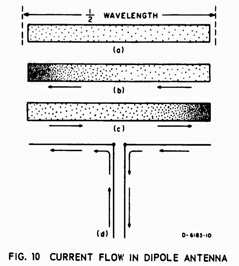
For example, below is Figure 10. It’s used to describe current flow in a dipole antenna.
The Field Guide reads:
Electric current in a conductor consists of the flow of small particles called electrons. Figure 10(a) represents a dipole with electrons in it. When the transmitter is turned off, the electrons distribute themselves evenly throughout the dipole, as shown. All electrons repel each other and try to get as far from each other as possible; that is how they achieve the uniform distribution show in Figure 10(a). When the transmitter is turned on, the electrons flow back and forth from end to end as shown in Figures 10(b) and 10(c). First the electrons flow to the left and crowded at one end as shown in Figure 10(b). Second, since the electrons repel each other, the push off to the right and get crowded together at the other end, as in Figure 10(c).
It then uses this description to talk about voltage and current distribution along a dipole antenna:
The difference between voltage (volts) and current (amperes) in a dipole is also illustrated by Figs. 10(b) and 10(c). You can see that the maximum flow of current is going to be in the middle of the dipole. An observer at the center of the dipole would see the electrons rush past, first one way and then the other. The center is the maximum current point. Very little current flows near the end of the dipole; in fact, at the extreme ends there is no current at all for there is no place for it to go. However, at the ends of the dipole, there is a great change of voltage; when the electrons are densely packed, this represents a negative voltages, and when there is a scarcity of electrons, it represents a positive voltage. Thus you can see that the voltage at each end swings alternately positive and and negative. An end of the dipole is a maximum voltage point.
A Field Guide to Simple HF Dipoles is packed with all kinds of goodies like this. Download it right now. This is just one of many fine military technical manuals that are now available for free from the Defense Technical Information Center.
Good stuff, Dan. Thanks for posting. Then I had to go look up Project Agile over at Wikipedia, and that was another education as well. From the intro: “Project AGILE was an Advanced Research Projects Agency (ARPA) project in the 1960s that investigated means for engaging in remote, limited warfare of an asymmetric type.”
To quote another famous voice from the ’60s: “Fascinating.”
Thanks Dan! I like these sorts of field guides.
Tnx! Great to pick up these guides!