
end fed antenna
The proof of the pudding…
The old saying goes, “The proof of the pudding is in the eating.” Of course, the same goes for amateur radio. We can argue about theory all day long, but it’s on-air performance that really matters.
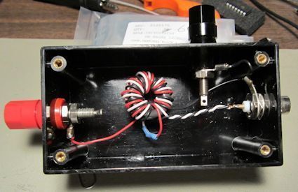
Last Saturday, I finally got a taste of some pudding. Last week, I put the latest version of the 9:1 unun that I’ve been experimenting with into a box (see below) and took it to the park to make some contacts.
I first had to decide on a length of wire for the radiator. I chose 30-ft. because that’s the length that Thom, W8TAM, had such good success with a couple of weeks ago. I also cut a 13-ft. counterpoise. I’m not sure exactly why I chose that length, but in the end, it seemed to work.
I shot the radiator up into a tree, connected the antenna and counterpoise to the unun, and connected the unun to an antenna analyzer to make a few measurements. On both 40m and 20m, the SWR that I measured was about 4:1, well within the range of the antenna tuner in my KX3. One amusing thing that I noted is that this measurement didn’t seem to change at all on 20m when I disconnected the counterpoise. It made a definite difference, though, on 40m.
Just for kicks, I also tried to measure the SWR without the unun. In both cases, the SWR was greater than 10:1.
I could have made more measurements, but I wanted to make some contacts. I tuned up on 40m and found AA3EJ calling CQ. He heard me right away, and we had a short QSO. By the way, I decided on working 40m as Rich, KA8BMA, had also come to the park today to try out his end-fed antenna, and he was on 20m.
Next, since the band sounded like it was in decent shape, I thought I’d give SSB a try. Tuning around 7200 kHz, I found an NPOTA station in Kentucky callling CQ. After a couple of tries, he finally heard me. That was actually my first SSB contact with the KX3.
I don’t think I can draw any real conclusions from this operation, except to say that the unun does indeed transform a high impedance to a lower one, and that I was radiating some RF with the antenna. More experimentation is definitely in order. I want to try a longer radiator and maybe different lengths of counterpoise. I also want to try building a 64:1 unun and see how the SWR measurements compare to the SWR measurements made with a 9:1 unun.
In addition, I want to get some smaller gauge antenna wire. I was using some 18 AWG wire that I had on the shelf. While that wire is great for stationary dipoles, I think more flexible, smaller gauge wire is more appropriate for field application.
I’m also going to be modify the 9:1 unun assembly. Rick noted in watching WG0AT videos that his unun used a panel-mount male BNC connector. That allows him to plug the unun directly into the radio, so there’s no need for a jumper cable. Rick bought a bunch and gave me one on Saturday. Thanks, Rick!
Playing with end-fed wire antennas and 9:1 ununs
For the past couple of weeks, I’ve been playing with end-fed wire antennas. Before I get into the nitty-gritty details, let me first make a distinction between end-fed half-wave antennas, such as the ones sold by LNR Precision and end-fed wires that use some kind of tuning to achieve a 50 Ω output impedance.
End-fed, half-wave antennas (EFHWs) are a half-wavelength long and are resonant antennas on the band of interest. They use some kind of matching network to trasnsform the very high impedance at the end of a half-wave wire to about 50 Ω. Generally, they are not usable on bands for which they are not a half wavelength long. You can’t, for example, generally use a 40m EFHW antenna on 20m.
End-fed wire antennas are a different beast. They are not a half-wavelength long, meaning that, if you choose the length of the radiator wisely, the impedance at the end of the wire will not be as high as the impedance of a half wavelength long wire.
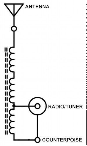 In many cases, the impedance can be transformed with the help of a 9:1 unun (unbalanced input to unbalanced output). See the figure at right. A 9:1 unun is a transformer that reduces the impedance at the input by a factor of 9. So, if you connect a length of wire that presents an impedance of about 450 Ω to the input, you’ll get an impedance of about 50 Ω on the output.
In fact, the 9:1 unun that I built is actually an autotransformer. Here’s a video that talks a little bit about autotransformers.
It’s relatively easy to build a 9:1 balun. One of the most common designs is to wind nine turns of a trifilar winding around a toroid core. Trifilar means that there are three wires wound simultaneously around the core. I’m not sure why there are nine turns, instead of say eight or ten, but I suspect that it’s a compromise between size and coupling. Nine turns yields sufficient coupling to ensure that the impedance transformation will take place without taking up too much space.
By the way, the ratio 9:1 isn’t really magic. You could choose to build a transformer with 7:1 or 12:1 ratio, but it just so happens that it’s much easier to build a 9:1 transformer than a 12:1 transformer.
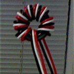 I built one on a T80-2 powdered iron core, using some 22-ga. wire that I scavenged from some four-conductor cable (see photo at left.) I got a little bit lucky in that the T80 core has a diameter just big enough to accommodate nine turns. Using different colored wires (red, black and white) made it easier to wire it up properly.
I didn’t do much engineering when it came to selecting the parts. I just happened to have a little bag of T80-2 cores that I’d purchased cheap at Dayton a couple of years ago. The short length of four-conductor cable was something that I’d salvaged from some previous project and had just thrown into my “wire box.” I haven’t done the calculations, but as built, I’d guess that it’s good up to 25 W or so. If you’re shooting for an unun to handle more power, then go with a T130 core and heavier gauge wire.
There’s also some question about which type of core to use. Some people wind their unun on ferrite cores instead of powered iron cores. One manufacturer even goes so far to say that they use a “custom mix” instead of one of the standard ferrite mixes (although I find it hard to believe at the relatively low quantities that they must be purchasing that they’re getting a truly custom mix). My friend, Thom, W8TAM, built his 9:1 unun using an FT82-61 core, and it works great. G3TXQ has performed a number of experiments with different core types, and with the antenna he used, found Type 2 powdered iron cores to be preferable.
So, how long a wire should you use for the antenna? It really depends on what bands you want to work. Mike, AB3AP, has calculated the lengths that give good results on various bands. Jack, VE3EED (SK), has also made this calculation. They differ slightly because VE3EED used the center of the bands in his calculations, while AB3AP used the center of the CW portion of the bands.
Last Saturday, I played around with an end-fed with a 36-ft. radiator and counterpoises of 13-ft. and 25-ft. To be honest, I wasn’t really happy with any of the configurations. The best I was able to do was achieve an SWR of 2:1 on 40m with the 36-ft. radiator and the 13-ft. counterpoise. Neither configuration yielded a satisfactory match on 20m.
Thom, on the other hand, used his 9:1 unun with a 30-ft. radiator and got fantastic results. He got great signal reports from an NPOTA station, a special event station in Georgia, and an operator working aeronautical mobile over Nebraska. So, there’s more experimentation in my future.
Update 8/19/2016
As I mentioned earlier, I wasn’t very happy with the results I was getting with the 9:1 unun that I had built earlier. So, yesterday evening, I went over to W8TAM’s house to compare his ununs to the one I just built. As I noted above, Thom had great success with his a couple of weeks ago.
The first thing we did was check that I had wired it properly. The only thing that we found is that instead of nine turns, I had only wound eight turns on the T80-2 core. I didn’t think it would make that big a difference, but Thom had a lot of wire, so we rewound the unun, this time making sure that I wound nine turns.
We connected two 1 kΩ resistors in parallel (to give us an input impedance of 500Ω) from input to ground and measured the output impedance on Thom’s Rig Expert AA-170 antenna analyzer. As I suspected, the extra turn made little difference. The SWR was 6.5:1 on 7150 kHz.
(As an aside here, I have to comment on the AA-170 antenna analyzer. In a word, it’s fantastic. One of the functions we used, for example, measures the SWR of antenna at the midpoints of all the amateur bands. This function is just perfect for testing the frequency response of baluns and ununs. It’s also graphs SWR across a frequency range. And, on top of all that, it’s about half the weight of my Palstar antenna analyzer. I think I’m going to dump the Palstar and get a RigExpert.)
At that point, we figured that the only thing it could be was the core. Fortunately, Thom had an FT82-61 ferrite core that he’d used to wind a QRP 9:1 unun. We cut three more lengths of wire, wound the unun, connected the 500 Ω load and measured the SWR.
WOW! The thing worked exactly as predicted! Here are the measurements:
| T80-2 | FT82-61 | |
| 7150 | 6.5 | 1.2 |
| 10125 | 4.1 | 1.1 |
| 14175 | 2.9 | 1.0 |
| 18118 | 2.3 | 1.1 |
| 21225 | 2.0 | 1.2 |
This was very puzzling and aggravating. As I noted above, G3TXQ found that the #2 powdered iron cores gave the best results. After a little Googling, I also found another ham, VK6SYF, who had success with a #2 core (http://vk6ysf.com/unun_9-1.htm). My friend KA8BMA built one using a T106-2 core, and it seems to be working right.
I bought the cores from a reputable dealer, so I don’t think that they’re bad, but I don’t know how else to account for the difference in performance. If you have any ideas on that, I’d love to hear them.
After getting that out of the way, we got into a discusssion of whether or not I really needed a 9:1 unun at all. The two radios that I use for portable operations are the Elecraft KX1 and the Elecraft KX3, both outfitted with antenna tuners. Both of them seem able to tune just about any length of wire not an exact half-wavelength, and that being the case, why bother with the 9:1 unun? The unun would just introduce more loss into the system.
Sounds like more experimentation is in order.
UPDATE 8/22/16
A couple of days ago, I e-mailed G3TXQ about my lack of success building a 9:1 unun with a T80-2 core, even though he seemed to have the best success with a #2 core. He said, “Using #2 cores will not give you a very accurate 9:1 impedance transformation, particularly if you use something as small as T80 size.” I found this kind of puzzling as he had said that in his experiments, he got the best results with a #2 core.
Anyway, since my friend Rich, KA8BMA, had wound his 9:1 unun on a T106-2 core, I thought I’d try this, too, and I just happened to have one in my box o’ toroids Well, wouldn’t you know it, the measurements are much, much better with the T106-2 core than they were with the T80-2 core.The SWR measured 1:1 on 20m and 17m, something like 1.8:1 on 40m, and 1.5:1 on 15m.
The frequency response of this unun isn’t as flat as the unun wound on the ferrite core, but it is certainly much better than the unun wound on the T80 core. The T106 core is only a quarter inch larger in diameter than the T80 core (1.06-in. vs. 0.80-in.). I wouldn’t have thought that a quarter-inch in diameter would make that much difference, but it did.
In researching this further, I discovered why. According to VK2TIP’s explanation of wide-band RF transformers, the impedance of the primary winding should be at least fives times the input impedance. Since my test input impedance is 500 Ω, that means the impedance of my primary winding should be at least 2500 Ω.
Using the online calculator at toroids.info, at a frequency of 14 MHz, and a primary winding of 27 turns, I get the following values:
| AL | Ω | |
| T80-2 | 5.5 | 352.7 |
| T106-2 | 13.5 | 865.7 |
| FT82-61 | 79 | 5066 |
The first thing to notice is that the inductance factor, AL, for the T-106-2 core is nearly twice that for the T80-2 core. I erroneously thought that they would be the same since the core material was the same. The higher value yields a higher inductance, and therefore, a better transformer.
Even so, the inductance is far from five times the input impedance. That’s why the FT82-61 ferrite core works much better for this application. With an AL of 79, the primary has an impedance of more than 5000 Ω, which gives a very good transformation.
As Steve, G3TXQ, pointed out in his e-mails to me, it really doesn’t matter if the impedance transformation is exactly 9:1 or some other value—especially if you will also be using an antenna tuner. In that case, winding your unun on a T106-2 core—or even better a T157-2 core that has an AL of 14—will work OK. If you’re like me, though, and want a 9:1 unun to actually give you a 9:1 transformation over most of the HF bands, then use a ferrite core.
One final note: A very nice feature of the toroids.info calculator is that it not only calculates the impedance for a particular number of windings, but also the length of the wire that you’ll need. On my first attempt at winding an unun on a T106-2 core, I greatly underestimated how much wire I needed and ended up throwing away that wire. I could have avoided doing that if I’d used the calculator.