
On July 1, 2020, this post will become obsolete as the 2020 Extra Class question pool goes into effect. Please refer to the post from the 2020 No Nonsense Extra Class Study Guide instead.
E4A – Test equipment: analog and digital instruments; spectrum and network analyzers, antenna analyzers; oscilloscopes; RF measurements; computer aided measurements
An instrument that amateur radio operators frequently use when experimenting or when debugging equipment is the oscilloscope, or simply just “scope.” Oscilloscopes have become more common in amateur radio shacks as the price has fallen and the technology has moved from analog to digital.
Analog oscilloscopes use amplifiers, filters, and other analog signal processing circuits to display an input signal on a cathode-ray tube, or CRT. Digital oscilloscopes, on the other hand, use an analog-to-digital converter to convert the input signal into a series of numbers, which are then processed by a computer and displayed on an LCD screen. All of these choices are correct when talking about the advantages of a digital vs. analog oscilloscope: (E4A05)
- Automatic amplitude and frequency numerical readout
- Storage of traces for future reference
- Manipulation of time base after trace capture
One of the most important oscilloscope specifications is its bandwidth. The bandwidth of an oscilloscope determines the maximum frequency at which the oscilloscope can accurately measure a signal. While the characteristics of the analog signal processing circuits determine the bandwith of an analog oscilloscope, sampling rate is the parameter that determines the bandwidth of a digital or computer-based oscilloscope. (E4A01) Similarly, the analog-to-digital conversion speed of the soundcard determines the upper frequency limit for a computer soundcard-based oscilloscope program. (E4A04)
Because digital oscilloscopes sample an input signal at discrete time intervals, it is possible to fool them into displaying an incorrect waveform. This phenomenon is called aliasing. The effect of aliasing in a digital or computer-based oscilloscope is that false signals are displayed. (E4A06) When using a computer’s soundcard input to digitize signals, the highest frequency signal that can be digitized without aliasing is one-half the sample rate. (E4A09)
Oscilloscope probes
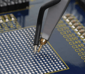
When making measurements at RF frequencies, it’s important to connect the probe’s ground connection as close to the location of the measurement as possible. Keeping the signal ground connection of the probe as short as possible is good practice when using an oscilloscope probe. (E4A11) Keeping this connection as short as possible reduces the noise picked up by the probe and reduces the inductance of the connection, which in turn, makes the measurement more accurate..
Good quality passive oscilloscope probes have an adjustable capacitor in them that needs to be adjusted so that the probe capacitive reactance is at least nine times the scope input capacitive reactance. When this capacitor is adjusted properly, we say that the probe is properly compensated, and the scope will display the waveform with as little distortion as possible.
How is the compensation of an oscilloscope probe typically adjusted? A square wave is displayed and the probe is adjusted until the horizontal portions of the displayed wave are as nearly flat as possible. (E4A13) High-quality oscilloscopes will have a special square-wave output specifically for the purpose of compensating probes.
Spectrum analyzers
Spectrum analyzers display the amplitude of signals in the frequency domain Frequency is the parameter a spectrum analyzer would display on the horizontal axis. (E4A02) The drawing below shows typical displays from an oscilloscope and a spectrum analyzer. Spectrum analyzers are very useful for troubleshooting problems. For example, a spectrum analyzer is used to display spurious signals from a radio transmitter. (E4A03)
Because spectrum analyzers are sensitive instruments, you need to be cautious when using them. For example, an important precaution to follow when connecting a spectrum analyzer to a transmitter output is to attenuate the transmitter output going to the spectrum analyzer. (E4A12) Not doing so could damage the spectrum analyzer because its input circuits are not designed to handle high power.
Antenna analyzers
One of the instruments that I think every amateur radio operator should have (or at least have access to) is the antenna analyzer. Antenna analyzers are versatile instruments that allow amateur radio operators to easily make antenna measurements, as well as other impedance measurements. They can even be used as low power RF signal generators.
An antenna analyzer is the instrument that would be best for measuring the SWR of a beam antenna. (E4A08) Actually, it’s the best instrument for measuring the SWR of any kind of antenna. That’s what they’re made for! When measuring antenna resonance and feed point impedance with a portable antenna analyzer, connect the antenna feed line directly to the analyzer’s connector. (E4B11)
An advantage of using an antenna analyzer compared to an SWR bridge to measure antenna SWR is that antenna analyzers do not need an external RF source. (E4A07) What this means is that you don’t need to connect your transmitter to the antenna to tune it. This is because they have an internal RF signal generator.
Frequency counters, logic analyzers
To measure the frequency of a signal, you use an instrument called a frequency counter. When selecting a frequency counter, an important specification is the maximum frequency. If you want to measure the frequency of a signal whose frequency is higher than the maximum frequency of your counter, you might use a prescaler. The purpose of a prescaler function on a frequency counter is to divide a higher frequency signal so a low-frequency counter can display the input frequency. (E4A14)
Most frequency counters work by counting the number of cycles of a signal during a given time period. An alternate method of determining frequency used by some counters is period measurement plus mathematical computation. An advantage of a period-measuring frequency counter over a direct-count type is that it provides improved resolution of low-frequency signals within a comparable time period. (E4A15)
The proper operation of a digital circuit depends on the output state of many nodes at specific times in a circuit. To ensure that a circuit is working properly, or to troubleshoot a circuit, you may want to use a logic analyzer. A logic analyzer displays multiple digital signal states simultaneously. (E4A10)

 Part I