
I don’t know that I’d call Clay Mitchell, W8JNZ (SK), my mentor exactly, but I did look up to him, both as a ham and as a person. I’ll always remember one thing that he told me. “Dan,” he said, “one of the best ways to learn about something is to ‘tinker’ with it.” He’d gotten this bit of advice from Dr. Richard Crane, W8CWN, who taught physics at the University of Michigan and was a a well-known science educator and great tinkerer.
I applied this bit of wisdom to the antenna that I use for portable ops. It’s nothing fancy—just a 66-ft. doublet—but by tinkering with it over the years, it’s a much better antenna than it was when I first built it.
It started with a KX1
It all started about 20 years ago when I decided that I wanted to operate portable and bought and built an Elecraft KX-1. Out of the box, the KX1 covers 40 meters and 20 meters, and you can buy an option to add 80 meters and 30 meters to the radio. I also purchased and built the optional automatic antenna tuner.
The user manual for the KX1 antenna tuner suggested using a wire antenna of 24 – 28 feet and one or more radials of at least 1/8-wavelength. It also suggests connecting these directly to the radio without a feed line. I cut four, 24-ft. lengths of wire from a spool of wire-wrap wire that I had scavenged from the dumpster of one of my employers, purchased a BNC-binding post adapter, connected the driven element to the red binding post and the three radials to the black binding post.

The tuner found a match for this antenna, but I was never really thrilled with the performance. I made some contacts, but with only 4 watts output, most of those contacts were a struggle. I struggled with this setup for a couple of years, but since I was really enjoying portable operation, I decided that some tinkering was in order.
A new antenna is born
In 2007, my 66-ft. doublet was born. Our club here in Ann Arbor, MI, ARROW, conducts mini-Field Days the we call AMP Team meetings every month. (AMP is short for ARROW Mobile and Portable.) We haul all kinds of radio gear out to a park and set up and operate. The gear you’ll find at one of these events includes HF, VHF, UHF, and even some microwave gear. Some club members, for example, are experimenting with AREDN mesh networking, and these meetings are a good place to test out their nodes without having to worry if their node’s antenna is line-of-sight with another node.
As I was contemplating what to use for an antenna for one of these outings, I scanned the shelves in my shack for antenna-making materials. I still had a fair amount of wire-wrap wire that I could use for the antenna itself, but what to use for feed line? When my eyes lit on a spool of twisted-pair wire, I thought why not give that a try? I cut two 33-ft. lengths of wire-wrap wire for the antenna elements and one 33-ft. length of twisted-pair wire to use as feed line.
As this was going to be an experimental antenna, I didn’t care too much how kludgey the thing looked. For the center insulator, I dug a ceramic dog bone insulator out of my box of antenna parts. To connect the feed line to the antenna elements, I used a couple of small wire nuts.

Cutting a 33-ft. length of wire for the feed line was actually a mistake. I figured that if I made the twisted pair feed line a half-wavelength long, then I’d have a relatively low impedance at the rig. Instead, in my haste, I cut it too short. 33 feet is only a quarter wavelength at 40 meters, which theoretically should have yielded a high impedance at the antenna input. In practice, however, the KX-1 managed to tune that antenna and feed line on 40 meters and 20 meters just fine. That just goes to show how much I know.
To hang up the antenna, I made a small loop at the end of each wire, and to that I tied some mason twine. I threw that twine up into a tree using a weighted tennis ball, and pulled up the antenna. One problem with this approach is that I was never able to get the antenna up all that high. Sometimes the antenna was less than 15 feet off the ground.
Another problem is that it took a long time to do this. It takes time to get two lines up into trees, raise the antenna, then tie off the lines. Not to mention that you need two trees relative close to one another. Sometimes, I would set up this antenna as an inverted-V, but I still had to find an appropriate tree for this.
Enter the KX3
In 2015, I bought a used KX3. Being a KX1 user, I had subscribed to the Elecraft-KX mailing list, and when someone offered to sell a KX3 with antenna tuner for about $1,200, I jumped on it. At first, I had visions of outfitting with with a PX3 band scope and some kind of amplifier to make a base station out of it, but when I found a good deal on a Flex 6400, I decided against that approach. The KX3 would be devoted to portable operation.
Because the KX3 antenna tuner has a wider range than the KX1 antenna tuner, I wasn’t anticipating any problems with it tuning the doublet. And, in fact, that was the case. The KX3 easily tunes the doublet on all bands between 40 meters and 10 meters.
POTA improvements
Improvements to the antenna accelerated once I started operating Parks on the Air (POTA). One of the first improvements was to purchase a 10-meter, telescoping, Spiderbeam fiberglass mast. With the Spiderbeam mast, I no longer have to throw lines up into trees. I slide a small eyelet into the top section of the telescoping mast and attach the center insulator of the antenna to the eyelet. I extend the mast and operate the doublet as an inverted V. No trees needed.
To anchor the telescoping mast, I pound three garden stakes into the ground at 120-degree intervals around the mast, then put a strap around the stakes and mast to hold the mast upright. This arrangement is much easier to set up than others that I’ve seen that use ropes and tent stakes, and it is very stable. It’s certainly stable enough for a two- or three-hour POTA activation.
To anchor the elements, I use two-pound exercise weights that I bought for a buck each at a local thrift shop. Using the weights, it’s easy to extend the elements to whatever length I need quickly. Overall, setting up the antenna is very quick. I can be on the air within 20 minutes of arriving at a park.
The next improvement that I thought I’d make is to find a center insulator that would provide better strain relief for the feed line. Searching the internet, I found a 3D-printed center insulator by an eBay seller who calls himself thecrazyham. He didn’t have anything designed for a twisted-pair feed line, but I guessed that a center insulator designed for 300 Ω twinlead would work just fine. It did work just fine, and as a bonus, it only cost five dollars!
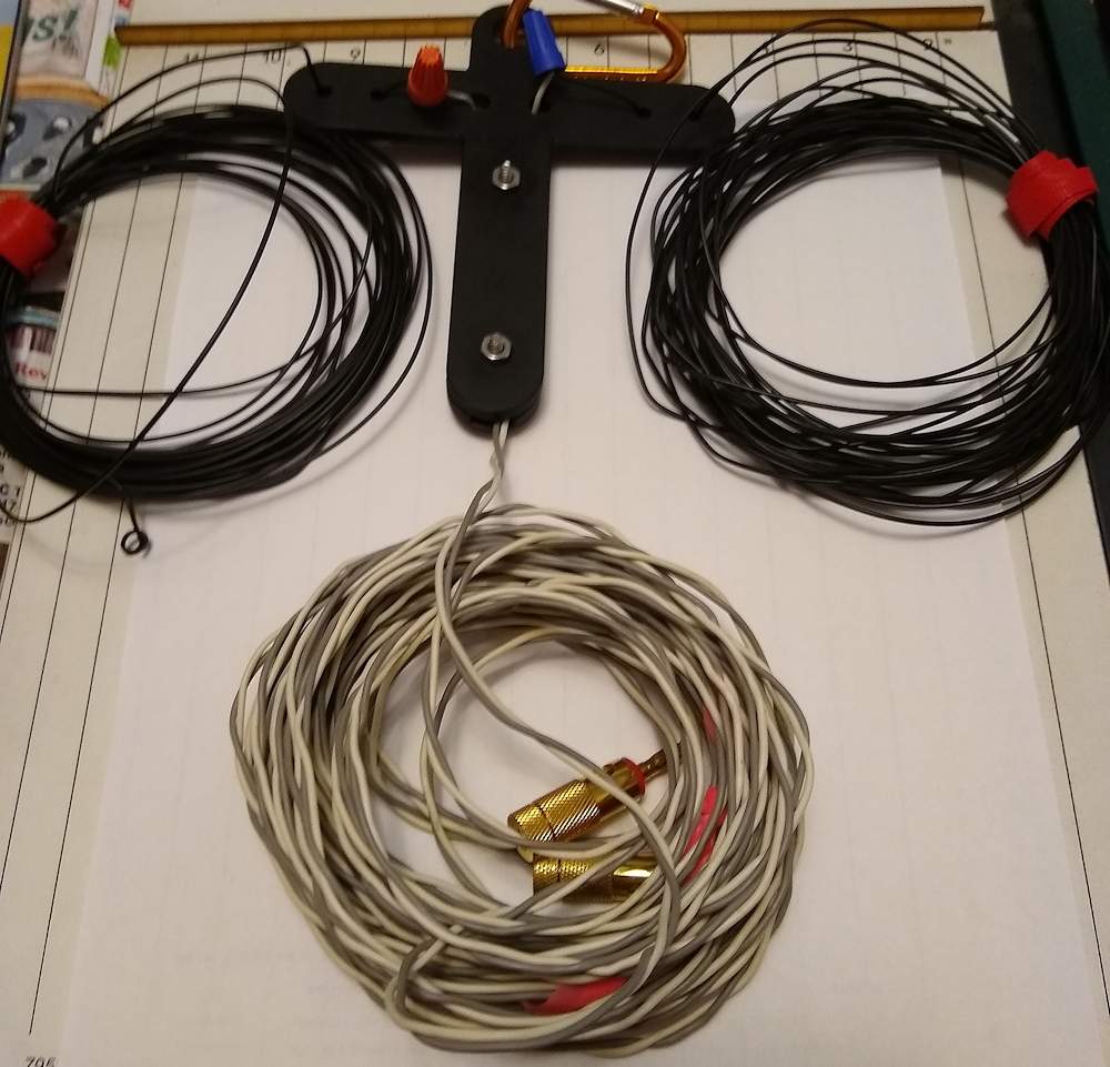
After acquiring the new center insulator, my friend, Rick, K8BMA gave me some 26-ga. Poly-STEALTH antenna wire. I cut two, 33-ft. lengths and connected them to the feed line with wire nuts again. I hadn’t had any trouble with the wire-wrap wire I was using, but this wire was made with antennas in mind. It’s really first-rate stuff. I don’t think it works any better than the wire-wrap wire, but it coils up neatly and fits nicely into the small toolbox I use to carry around POTA station.
A “real” feed line
Whenever I was asked about my POTA antenna, I would brag about the twisted-pair feed line. I was rather proud that I thought to use twisted-pair wire as a feed line, and that it actually worked. But, a couple of months ago, my friend Paul, KW1L, bought a Cobra antenna. Before putting it up at his house, he asked if we could take it on a POTA activation and try it out. I agreed, and one morning, we took it up to the Island Lake Recreation Area.
Band conditions were good that morning, but even so, it seemed like the antenna was performing at least a little better than my doublet. Paul said, “Well, sure, it’s because the Cobra antenna has a real feed line.”
So, I decided to try a “real feed line” on my doublet. It just so happened that I had a 100-ft. roll of 300 Ω twinlead that I purchased at a dollar store many years ago. I cut off a 35-ft. hunk of it, soldered it to the antenna elements, and put some banana plugs on the other end of it. After using this antenna for a couple of months now, I feel that I have to swallow my pride a little and say that the antenna with the 300 Ω feed line does work a little better than it did with the twisted-pair feed line. I’m guessing that it’s because the twisted-pair feedline has a higher loss than the twinlead.

My latest improvement is to use a 4:1 balun between the feedline and the antenna tuner. Until just recently, I was connecting the feedline directly to the KX3 antenna tuner, but the fellow who sells Cobra antennas recommends using a 4:1 balun, so I thought that doing so might improve my antenna’s performance as well.
Several years ago, I purchased a couple of W1CG current balun kits at a hamfest, and now was the time to build one. This is a really great kit, and if you ever see one at a hamfest or wherever, buy it. The New Jersey QRP Club that sponsored this kit is now defunct (despite the website still being online), and the kits are no longer available. (I’ve been thinking about kitting up some and selling them, but that’s a discussion for another day.) The instruction manual is still available, though, and it’s not hard to find the parts.
If you’re at all interested in baluns and how they work, you should download the instructions. They contain a great description of how baluns work and the difference between voltage baluns and current baluns.
At any rate, I built one of the kits, and have started to use the balun on my POTA activations. I can’t say for sure how much the balun has improved my results, but it certainly hasn’t hurt them, so I’m going to continue to use it.
Tinkering gets results
If you take away only one thing from this article, take away the idea that tinkering with something gets results. The antenna that I’m using today is basically the same antenna that I built 20 years ago, but the tweaks that I’ve made have significantly improved its performance and its ease of use.
One final note: I recognize that much of my success is due to the magic of the Elecraft antenna tuner. I have used this antenna with other antenna tuners, including the inexpensive Z-match tuners you can get from Ali Express or Amazon. It should also work well with the Emtech ZM-2 antenna tuner. If you purchase and tinker with this antenna and one of these tuners, please let me know how it works out for you.
Twisted pair, zip cord and or speaker wires make lousy lossy transmission lines because
they use PVC for the dielectric/insulation, which is fine for DC, AC power and audio
but very lossy at radio and microwave frequencies. Transmission lines for RF use loss
loss polyethylene for the dielectric/insulation. Teflon is even better but costs more.
At radio and microwave frequencies all plastics are not the same. The details matter.
I didn’t find the twisted-pair wire to be a “lousy” feed line. I made many contacts using that wire, but the twinlead does seem to be a bit better.
Let me clarify, I did not mean that twisted pair feed lines with PVC insulation
were full of lice or that it wouldn’t work. It doesn’t work well and is unsuited
for RF/microwave applications. See wikipedia’s or any coaxial cable table.
PVC is not used as a dielectric because it is lossy (lousy). PVC works great in
RF/HF welding machines because it readily absorbs RF energy. The plastics
that don’t work in RF/HF welding machines PE(polyetheylene), PTFE(teflon),
PE foam etc.are used in RF/microvawe cables. That you “made many contacts”
is a credit to your operating skills not to the suitability of PVC. Also the small
gauge wire like AWG24 or AWG26 can add 10-30 ohms or so of skin effect
resistance to your antenna system depending on frequency and length.
https://en.wikipedia.org/wiki/Coaxial_cable
https://www.weldmaster.com/hubfs/Machines/RFlex/PDFs/Weldability%20Chart%20-%20RF.pdf
https://voltage-disturbance.com/engineering-calculators/skin-effect-calculator/
Look at any RF/microwave transmission line table. https://en.wikipedia.org/wiki/Coaxial_cable
They don’t use PVC for the dielectric because it’s lousy (lossy). It does RF/HF welding quite nicely.
https://www.weldmaster.com/hubfs/Machines/RFlex/PDFs/Weldability%20Chart%20-%20RF.pdf
Polyethylene and Teflon don’t don’t work in RF/HF welding machines at all. They are used for coax.
Also the 24AWG or 26AWG wire adds 10-30 Ohms or so resistance to your antenna system.
https://voltage-disturbance.com/engineering-calculators/skin-effect-calculator/
I’ve also made the switch from old wire wrapping wire to 26 AWG PolyStealth. I will say the PolyStealth survives a lot better when limbs come down on it… but they are both just wire. I’ve also switched to Wago LeverNuts. They make changing out wire a snap (literally).
Keep Tinkering!!!
I have been using one of the four sets of CAT5 for at least a decade.
Disassembling the CAT5 is a little tedious, but you get good at it.
The fibreglass strand inside the PE jacket facilitates stripping it off, in case you were wondering what the fibreglass was there for.
I actually use one pair for one leg of a doublet, another pair for the other side, and the remaining 2 pairs for a feed (if you need both lengths.)
It works fine!
I string it up with nylon plumbers line.
Nylon doesn’t rot.
I’m devising a sort of shape to wrap it up on, for transport, and keep it untangled.
Very light. Cheap .
Course I use match. Balanced.
A Balun could let you use your average matcher
VE3GYY