
• Skip to primary navigation
  • Skip to main content
  • Skip to primary sidebar
  • Skip to footer

KB6NU's Ham Radio Blog

KB6NU's Ham Radio Blog
  • HOME
  • Study Guides
  • Teach a One-Day Tech Class
  • W8SRC Repeater Guide
  • Advertise
  • Hire Me

Extra Class question of the day: Wire and phased vertical antennas

September 19, 2012 By Dan KB6NU Leave a Comment

There are many ways to put up antennas that are directional. Yagis are directional antennas, but they require a structure, such as a tower, to get them high in the air. One way to get directionality without a tower is to use phased vertical arrays.

In general, the phased vertical array consists of two or more quarter-wave vertical antennas. The radiation pattern that the array will have depends on how you feed the vertical antennas.

So, for example, the radiation pattern of two 1/4-wavelength vertical antennas spaced 1/2-wavelength apart and fed 180 degrees out of phase is a figure-8 oriented along the axis of the array. (E9C01) The radiation pattern of two 1/4-wavelength vertical antennas spaced 1/4-wavelength apart and fed 90 degrees out of phase is a cardioid. (E9C02) The radiation pattern of two 1/4-wavelength vertical antennas spaced 1/2-wavelength apart and fed in phase is a Figure-8 broadside to the axis of the array. (E9C03)

A rhombic antenna is often used for receiving on the HF bands. A basic unterminated rhombic antenna is described as bidirectional; four-sides, each side one or more wavelengths long; open at the end opposite the transmission line connection. (E9C04) The disadvantages of a terminated rhombic antenna for the HF bands is that the antenna requires a large physical area and 4 separate supports. (E9C05) Putting a terminating resistor on a rhombic antenna changes the radiation pattern from bidirectional to unidirectional. (E9C06)
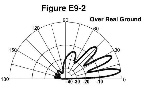
Figure E9-2: Elevation Pattern

The type of antenna pattern over real ground that is shown in Figure E9-2 is an elevation pattern. (E9C07) The elevation angle of peak response in the antenna radiation pattern shown in Figure E9-2 is 7.5 degrees. (E9C08) The front-to-back ratio of the radiation pattern shown in Figure E9-2 is 28 dB. (E9C09) 4 elevation lobes appear in the forward direction of the antenna radiation pattern shown in Figure E9-2. (E9C10)

How and where you install an antenna affects its radiation pattern. For example, the far-field elevation pattern of a vertically polarized antenna is affected when it is mounted over seawater versus rocky ground. What happens is that the low-angle radiation increases. (E9C11) The main effect of placing a vertical antenna over an imperfect ground is that it reduces low-angle radiation. (E9C13) When constructing a Beverage antenna, remember that it should be one or more wavelengths long to achieve good performance at the desired frequency. (E9C12)

Related posts:

  1. Extra Class question of the day: Antenna patterns: gain as a function of pattern; antenna design (computer modeling of antennas); Yagi antennas
  2. 2020 Extra Class study guide: E9C – Practical wire antennas; folded dipoles; phased arrays; effects of ground near antennas
  3. 2016 Extra Class Study Guide: E9C – Wire and phased-array antennas
  4. 2020 Extra Class study guide: E9H – Receiving Antennas: radio direction finding antennas; Beverage antennas; specialized receiving antennas; long-wire receiving antennas

Filed Under: Antennas, Extra Class Question of the Day

Reader Interactions

Leave a Reply Cancel reply

Your email address will not be published. Required fields are marked *

Primary Sidebar

No Nonsense Technician Class License Study Guide (for tests given between July 2026 and June 2030)

New No Nonsense Technican Class Study Guide now available!

The 2026 version of my Tech Class study guide is now available, and as always, the PDF version is FREE!. The ePub version costs $11.97, and a Kindle version and paperback version will be available on Amazon shortly.

Click here to get all of my "No Nonsense" study guides.

Also available: The CW Geek's Guide to Having Fun with Morse Code

W5SWL.Com
Retevis Ailunce H1 DMR Radio
DXpander: Cobweb antennas, Laser Cutting

You’ve got mail!

Enter your email address below and get an email every time I publish a new post.

Email


I frequently teach classes to help newcomers get their licenses. The next class will take place on Saturday, October 10, 2026 on the University of Michigan campus. Click here for more information.

If you can't make the class, subscribe to the mailing list to be notified of when the next class will be held.

You can always download my free study guide, and if you have any questions about the classes, or amateur radio in general, please feel free to email me directly.

Support KB6NU.Com

Donate $7.30 and get two of these cool stickers. Measuring 4.25-in. W by 2.75-in. H, it's perfect for your car, your shack, or wherever!

Contact me

If you have a question or comment about one of my blog posts, or a question about any of the material in my study guides, or just a question about ham radio in general, you can email me at [email protected].

Blogs You Should Also Read

  • AE5X: A CW-centric blog from Kingswood, Texas
  • K0LWC Blog
  • LA3ZA Ham Radio Blog
  • Little Radios, Big Fun – WB3GCK
  • Mr. Vacuum Tube's Blog
  • Radio Artisan – K3NG
  • The K0NR Weblog
  • VE3WDM's QRP Ham Radio Blog
  • W2LJ’s Blog

Ham Radio Websites

  • Dashtoons – The Hammin' Comedy by Jeff K1NSS

Podcasts

  • ICQ Podcast
  • Linux in the Ham Schack
  • No Nonsense Amateur Radio Podcast
  • Resonant Frequency Amateur Radio Podcast

Recent Comments

  • Bulin 47 AI on ICQPodcast Episode 485 – World Cup Special Event Station
  • Jesse Alexander on What do you think of this artwork for the ham radio EMF Explorer
  • CADProps on My first go at 3D printing not quite a success
  • Dan KB6NU on A Media Guide to Amateur Radio
  • Steve Stroh N8GNJ on A Media Guide to Amateur Radio

Meta

  • Log in
  • Entries feed
  • Comments feed
  • WordPress.org

Footer

Copyright © 2026 Daniel M. Romanchik, KB6NU · Log in