
The 2019 question pool is out, and I’ve started updating the No Nonsense General Class Study Guide. Here’s the first chapter. As always, comments are welcome…Dan
Reactance; inductance; capacitance; impedance; impedance matching
When an alternating current (AC) is applied to capacitors and inductors, they oppose the flow of current, but in a more complex way than the way resistors oppose the flow of direct current. The opposition to alternating currents by capacitors and inductors is called reactance, and we use the letter X to stand for reactance. The unit of reactance is the ohm.
QUESTION: What is reactance? (G5A02)
ANSWER: Opposition to the flow of alternating current caused by capacitance or inductance
QUESTION: What unit is used to measure reactance? (G5A09)
ANSWER: Ohm
QUESTION: Which of the following causes opposition to the flow of alternating current in an inductor? (G5A03)
ANSWER: Reactance
QUESTION: Which of the following causes opposition to the flow of alternating current in a capacitor? (G5A04)
ANSWER: Reactance
The reactance caused by a capacitor or inductor depends on the frequency of the AC source. You calculate the reactance caused by an inductor with the equation:
XL = 2πfL
where XL is the inductive reactance in ohms (Ω), f is the frequency of the AC applied to the inductor in Hertz (Hz), and L is the inductance in henries. As you can see, as the frequency of the AC increases, so does the reactance of the inductor.
QUESTION: How does an inductor react to AC? (G5A05)
ANSWER: As the frequency of the applied AC increases, the reactance increases
You calculate the reactance caused by a capacitor with the equation:
XC = 1/(2πfC)
where XC is the capacitive reactance in ohms (Ω), f is the frequency of the AC applied to the capacitor in Hertz (Hz), and C is the capacitance in farads. As you can see from the equation, as the frequency of the AC increases, the capacitive reactance decreases.
QUESTION: How does a capacitor react to AC? (G5A06)
ANSWER: As the frequency of the applied AC increases, the reactance decreases
Resistors also oppose the flow of current in an AC circuit. When an AC circuit contains both resistance and reactance, the resistance and reactance combine in a complex way to oppose the flow of current in the circuit. We call this combination impedance, and impedance is measured in ohms.
QUESTION: What is impedance? (G5A01)
ANSWER: The opposition to the flow of current in an AC circuit
When setting up an amateur radio station, it is important to know the input and output impedances of devices and circuits that you will connect together. When these two impedances are equal, they are said to “match” one another. For example, when the output impedance of a transmitter is 50 ohms and the input impedance of an antenna is 50 ohms, they match one another.
If the output impedance of a circuit or device (often called the “source”) does not match the input impedance of the circuit or device that you connect to it (often called the “load”), the source will not deliver the maximum amount of power to the load. Impedance matching is, therefore, important so the source can deliver maximum power to the load.
QUESTION: What happens when the impedance of an electrical load is equal to the output impedance of a power source, assuming both impedances are resistive? (G5A07)
ANSWER: The source can deliver maximum power to the load
Impedance matching is so important that engineers have devised several different types of circuits and devices to match the output impedance of a source to the input impedance of a load. One way to do this is to insert an LC network, which is a circuit made up of inductors (L) and capacitors (C), between the source and the load. You could also use an impedance-matching transformer or a length of transmission line.
QUESTION: What is one reason to use an impedance matching transformer? (G5A08)
ANSWER: To maximize the transfer of power
QUESTION: Which of the following devices can be used for impedance matching at radio frequencies? (G5A10)
ANSWER: All these choices are correct
- A transformer
- A Pi-network
- A length of transmission line
QUESTION: Which of the following describes one method of impedance matching between two AC circuits? (G5A11)
ANSWER: Insert an LC network between the two circuits
The Decibel; current and voltage dividers; electrical power calculations; sine wave root-mean-square (RMS) values; PEP calculations
Kirchoff’s Current Law states that the sum of currents entering a circuit node must equal the sum of the currents leaving the node. In the circuit below, we have a parallel circuit made up of two resistors. In this circuit, I = I1 + I2, or to put it another way, the total current entering a parallel circuit equals the sum of the currents through each branch, or in this case, the sum of the currents thought each resistor.
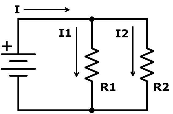
QUESTION: How does the total current relate to the individual currents in each branch of a purely resistive parallel circuit? (G5B02)
ANSWER: It equals the sum of the currents through each branch
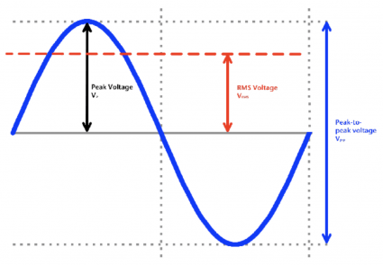
In amateur radio, we have to deal with AC voltages and currents all the time. AC powers our radios in our base stations and radio signals are AC signals, and especially sinusoidal signals, that is signals that look like sine waves. A sine wave is shown in the figure below.
Three important parameters of a sinusoidal AC signal are:
-
The peak value, Vp, which is the highest voltage value.
-
The peak-to-peak value, which is the difference between the highest value and the lowest value. In a sine wave, Vp-p is twice the value of Vp.
-
The root mean square, or RMS value, VRMS. The RMS value is the voltage that causes the same power dissipation as a DC voltage of the same value. For an AC sinusoidal signal, the RMS value is .707 times the peak value.

QUESTION: What value of an AC signal produces the same power dissipation in a resistor as a DC voltage of the same value? (G5B07)
ANSWER: The RMS value
QUESTION: What is the RMS voltage of a sine wave with a value of 17 volts peak? (G5B09)
ANSWER: 12 volts
VRMS = Vp x .707 = 17 V x .707 = 12 volts
You can also calculate the peak-to-peak voltage of an AC signal if you know the RMS value:
Vpeak = VRMS ÷ 0.707 = VRMS x 1.414
The peak to peak voltage, or Vp-p, is twice that value, or VRMS x 2.828.
QUESTION: What is the peak-to-peak voltage of a sine wave with an RMS voltage of 120.0 volts? (G5B08)
ANSWER: 339.4 volts
Vp-p = VRMS x 2.828 = 120 x 2.828 = 339.4 volts.
When the voltage and current are in phase, the power delivered by an AC signal is equal to the RMS voltage times the current, or
P (watts) = VRMS x I
Using Ohm’s Law, we can show that:
P = V2RMS / R
P = I2RMS x R
For DC circuits, the equations are:
P (watts) = V x I
P = V2/ R
P = I2 x R
Let’s look at some examples:
QUESTION: How many watts of electrical power are used if 400 VDC is supplied to an 800 ohm load? (G5B03)
ANSWER: 200 watts
P = V2/ R = 4002/800 = 160,000 / 800 = 200 watts
QUESTION: How many watts of electrical power are used by a 12 VDC light bulb that draws 0.2 amperes? (G5B04)
ANSWER: 2.4 watts
P = V x I = 12 x 0.2 = 2.4 watts
QUESTION: How many watts are dissipated when a current of 7.0 milliamperes flows through a 1250 ohm resistance? (G5B05)
ANSWER: Approximately 61 milliwatts
P = I2 x R = 0.0072 x 1,250 ≈ .061 W ≈ 61 milliwatts
These formulas can also be used to calculate RF power and RF voltages and currents.
QUESTION: What would be the RMS voltage across a 50 ohm dummy load dissipating 1200 watts? (G5B12)
ANSWER: 245 volts
V2RMS = P / R = 50 x 1,200 = 60,000, √60,000 ≈ 245 volts
A term sometimes used to describe the power output of a phone signal is peak envelope power (PEP). This is the maximum instantaneous power achieved when transmitting a phone signal. For an unmodulated carrier, the peak envelope power is equal to the average power. When transmitting a single sideband signal, though, the amplitude will vary with time, and the average power may be considerably less.
Here are some examples:
QUESTION: What is the ratio of peak envelope power to average power for an unmodulated carrier? (G5B11)
ANSWER: 1.00
QUESTION: What is the output PEP of an unmodulated carrier if an average reading wattmeter connected to the transmitter output indicates 1060 watts? (G5B13)
ANSWER: 1060 watts
QUESTION: What is the output PEP from a transmitter if an oscilloscope measures 200 volts peak-to-peak across a 50 ohm dummy load connected to the transmitter output? (G5B06)
ANSWER: 100 watts
VRMS = Vp x 0.707 = Vp-p/2 x 0.707 = 100 x 0.707 = 70.7 V
P = V2RMS ÷ R = 70.72 ÷ 50 = 100 watts
QUESTION: What is the output PEP from a transmitter if an oscilloscope measures 500 volts peak-to-peak across a 50 ohm resistive load connected to the transmitter output? (G5B14)
ANSWER: 625 watts
VRMS = Vp x 0.707 = Vp-p/2 x 0.707 = 250 V x 0.707 = 176.75 V
P = V2RMS ÷ R = 176.752 ÷ 50 = 625 watts
Often, we’re not concerned with the actual power, but with the ratio of power input to power output. For example, if an amplifier has a gain of 10, we know that if we input a 1 W signal, we’ll get 10 W out. Quite often, you’ll see this ratio specified in decibels, or dB.
The formula for calculating power ratios in dB is:
A(dB) = 10 x log10 (P2/P1)
Using this formula, you can see that a two-times increase or decrease in power results in a change of about 3 dB.
QUESTION: What dB change represents a factor of two increase or decrease in power? (G5B01)
ANSWER: Approximately 3 dB
A(dB) = 10 x log10 (P2/P1) = 10 x log10 (2/1) = 10 x .301 ≈ 3 dB
When P2/P1 is less than 1, it means there is a power loss.
QUESTION: What percentage of power loss would result from a transmission line loss of 1 dB? (G5B10)
ANSWER: 20.6 percent
P2/P1 = 10(A(dB)/10) = 10-0.11 = .794
Note that since this is a power loss, the value we use in the equation is -1 dB, and the power loss is 20.6% because P2/P1 is equal to 79.4%.
Resistors, capacitors, and inductors in series and parallel; transformers
Connecting components in series and in parallel will affect their effective values. For example, if you connect resistors in series, the effective resistance is the sum of the individual resistances.
QUESTION: Which of the following components increases the total resistance of a resistor? (G5C03)
ANSWER: A series resistor
IQUESTION: f three equal value resistors in series produce 450 ohms, what is the value of each resistor? (G5C05)
ANSWER: 150 ohms
If Rtotal = 450 ohms = 3 x R, then R = 450 ohms/3 = 150 ohms.
Connecting resistors in parallel will decrease the circuit resistance. The equation that you use to calculate the total resistance of resistors in parallel is:
Rtotal = 1/(1/R1 + 1/R2 + 1/R3…)
When the resistors are all equal, simply divide the value of one of the resistors by the number of resistors in parallel. Let’s look at some examples”
QUESTION: What is the total resistance of three 100 ohm resistors in parallel? (G5C04)
ANSWER: 33.3 ohms
Rtotal = 100 / 3 = 33.3 ohms
QUESTION: What is the total resistance of a 10 ohm, a 20 ohm, and a 50 ohm resistor connected in parallel? (G5C15)
ANSWER: 5.9 ohms
Rtotal = 1/(1/10 + 1/20 + 1/50) = 1/0.17 ≈ 5.9 ohms
Inductors work the same way as resistors. You would, therefore, add an inductor in series with an inductor to increase circuit inductance and connect inductors in parallel to decrease circuit inductance.
QUESTION: Which of the following components should be added to an inductor to increase the inductance? (G5C14)
ANSWER: An inductor in series
Here are a couple of examples:
QUESTION: What is the inductance of a 20 millihenry inductor connected in series with a 50 millihenry inductor? (G5C11)
ANSWER: 70 millihenrys,
QUESTION: What is the inductance of three 10 millihenry inductors connected in parallel? (G5C10)
ANSWER: 3.3 millihenrys
Capacitors, however, combine in the opposite way. You connect capacitors in parallel to increase the total capacitance. The equation that you use to calculate the total capacitance of two or more cpacitors in parallel is Ctotal = C1 + C2 + C3… Connecting capacitors in series decreases the total capacitance. The equation that you use to calculate the total capacitance of capacitors in series is Ctotal = 1/(1/C1 + 1/C2 + 1/C3…)
QUESTION: Which of the following components should be added to a capacitor to increase the capacitance? (G5C13)
ANSWER: A capacitor in parallel
QUESTION: What is the capacitance of a 20 microfarad capacitor connected in series with a 50 microfarad capacitor? (G5C12)
ANSWER: 14.3 microfarads
Ctotal = 1/(1/C1 + 1/C2) = 1/(1/20 + 1/50) = 1/.07 = 14.3 microfarads.
QUESTION: What is the capacitance of three 100 microfarad capacitors connected in series? (G5C09)
ANSWER: 33.3 microfarads
Ctotal = 1/(1/C1 + 1/C2 + 1/C3) = 1/(1/100 + 1/100 + 1/100) = 1/.03 = 33.3 microfarads. As you can see, if all the capacitors are equal, all you need to do is to divide the value of one of the capacitors by the number of capacitors in series, or in this case, Ctotal = 100 microfarads / 3 = 33.3 microfarads.
When working with capacitors, it’s important to take note of how the capacitance is specified. The capacitance is sometimes specified in microfarads (μF), sometimes in nanofarads (nF), and sometimes in picofarads (pF). A microfarad is 1,000 nanofarads, and a nanofarad is 1,000 picofarads. Here are a couple examples of how to convert between units:
QUESTION: What is the value in nanofarads (nF) of a 22,000 picofarad (pF) capacitor? (G5C17)
ANSWER: 22
QUESTION: What is the value in microfarads of a 4700 nanofarad (nF) capacitor? (G5C18)
ANSWER: 4.7
Where it’s really important to keep this in mind is when you’re working with some capacitors whose capacitance is specified in nanofarads and others who are specified in picofarads. For example,
QUESTION: What is the equivalent capacitance of two 5.0 nanofarad capacitors and one 750 picofarad capacitor connected in parallel? (G5C08)
ANSWER: 10.750 nanofarads
750 pF is equal to 0.75 nF, and because the capacitors are connected in parallel, the equivalent capacitance is equal to the sum of all the capacitances. Ctotal = C1 + C2 + C3 = 5 nF +5 nF + 0.75 nF = 10.750 nanofarads.
Inductors exhibit a behavior called mutual inductance. Mutual inductance occurs when a current flowing through one inductor induces a current in a nearby inductor. We use this behavior to create components called transformers. The simplest transformer has two windings: a primary winding and a secondary winding. When a current flows through a primary winding, it induces a current in the secondary winding and causes a voltage to appear across the secondary winding.
QUESTION: What causes a voltage to appear across the secondary winding of a transformer when an AC voltage source is connected across its primary winding? (G5C01)
ANSWER: Mutual inductance
The voltage across the secondary winding will be equal to the voltage across the primary times the ratio of the number of turns in the secondary to the number of turns in the primary. When the number of turns in the secondary winding is greater than the number of turns in the primary winding, the voltage across the secondary winding will be great than the voltage across the primary winding, and the transformer is called a step-up transformer.
When the number of turns in the secondary winding is less than the number of turns in the primary winding, the voltage across the secondary winding will be less than the voltage across the primary winding, and the transformer is called a step-down transformer.
QUESTION: What is the RMS voltage across a 500-turn secondary winding in a transformer if the 2250-turn primary is connected to 120 VAC? (G5C06)
ANSWER: 26.7 volts
Secondary voltage = primary voltage x primary turns/secondary turns = 120 V x 500/2250 = 120 x 0.222 = 26.7 V.
By reversing a transformer’s windings, that is connecting an input voltage to a transformer’s secondary winding and connecting the primary windings to the output circuit, you make a step-up transformer act like a step-down transformer and vice versa.
QUESTION: What happens if a signal is applied to the secondary winding of a 4:1 voltage step-down transformer instead of the primary winding? (G5C02)
ANSWER: The output voltage is multiplied by 4
Doing this is not necessarily a good idea, however. Current in the primary winding of a step-up transformer is higher than the current in the secondary, so the conductor of the primary winding of many voltage step-up transformers is larger in diameter than the conductor of the secondary winding. If you use a step-down transformer as a step-up transformer by connecting the input voltage to the secondary winding, the wire in the winding may not be able to handle the higher current and burn out.
QUESTION: Why is the conductor of the primary winding of many voltage step-up transformers larger in diameter than the conductor of the secondary winding? (G5C16)
ANSWER: To accommodate the higher current of the primary
Transformers are also used to transform impedances. The impedance ratio is also related to the turns ratio, but the transformation is equal to the square of the turns ratio. Here’s an example:
QUESTION: What is the turns ratio of a transformer used to match an audio amplifier having 600 ohm output impedance to a speaker having 4 ohm impedance? (G5C07)
ANSWER: 12.2 to 1
Turns ratio = √(output impedance/input impedance) = √150 = 12.2.
“currents thought each resistor.” –> “currents through each resistor.”
‘Let’s look at some examples”’ –> ‘Let’s look at some examples:’
I hate typos. :) Thanks, Dave.
Thank you so much for this Kristi! It seems intuitive but I feel like I have learned general class study guide electrical principles many of these lessons the hard way.It is nice to see them all in one place as a reminder
QUESTION: What would be the RMS voltage across a 50 ohm dummy load dissipating 1200 watts? (G5B12)
ANSWER: 245 volts
V2RMS = P / R = 50 x 1,200 = 60,000, √60,000 ≈ 245 volts
Correction:
V2RMS = P X R = 50 x 1,200 = 60,000, √60,000 ≈ 245 volts
Can’t seem to make the “2” a superscript in either of the above. Sorry. But you know it means “squared”.
Thank you for this article.
73,
Randy