
Integrated circuits (ICs) are now an integral part (pun intended) of amateur radio electronics. There are several different technologies used to manufacture ICs including transistor-transistor logic, or TTL; complementary metal-oxide semiconductor, or CMOS; and BiCMOS, which uses a combination of bipolar and CMOS transistors.
CMOS is arguably the most common type of digital IC. One of the reasons for this is that CMOS logic devices consume less power than TTL devices. They also are more immune to power supply noise and noise on the inputs because the input switching threshold is about one-half the power supply voltage.
QUESTION: What is an advantage of CMOS logic devices over TTL devices? (E6C05)
ANSWER: Lower power consumption
QUESTION: Why do CMOS digital integrated circuits have high immunity to noise on the input signal or power supply? (E6C06)
ANSWER: The input switching threshold is about one-half the power supply voltage
BiCMOS logic is an integrated circuit logic family that uses both bipolar and CMOS transistors. An advantage of BiCMOS logic is that it has the high input impedance of CMOS and the low output impedance of bipolar transistors.
QUESTION: Which of the following is an advantage of BiCMOS logic? (E6C04)
ANSWER: It has the high input impedance of CMOS and the low output impedance of bipolar transistors
Some devices have three different output states: 0, 1, and a high-impedance state. We call these devices tri-state logic devices. The high-impedance state allows you to connect many of them to a common bus. When a device’s outputs are in the high-impedance state, they act as if they are disconnected.
QUESTION: What is tri-state logic? (E6C03)
ANSWER: Logic devices with 0, 1, and high-impedance output states
When working with digital ICs, it is important to recognize the various symbols for the different types of logic gates. Figure E6-3 shows the schematic symbols for the most common logic gates. It includes the following:
- AND gate
- NAND gate
- OR gate
- NOR gate
- NOT (inverter)
- Not a valid logic gate symbol
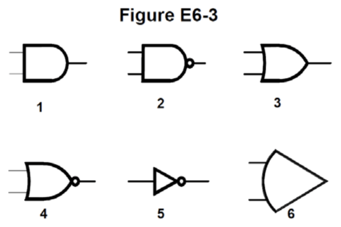
QUESTION: In Figure E6-3, what is the schematic symbol for a NAND gate? (E6C08)
ANSWER: 2
QUESTION: In Figure E6-3, what is the schematic symbol for a NOR gate? (E6C10)
ANSWER: 4
QUESTION: In Figure E6-3, what is the schematic symbol for the NOT operation (inverter)? (E6C11)
ANSWER: 5
When designing circuits with digital ICs, you may not use all of the inputs of the gates in that IC. To set that input to a digital 1 or 0, you might use a pull-up resistor or a pull-down resistor. A pull-up would be connected to the positive supply line while a pull-down would be normally connected to ground. Pull-up resistors are also often used on the output of a digital circuit to prevent the output from floating.
QUESTION: What best describes a pull-up or pull-down resistor? (E6C07)
ANSWER: A resistor connected to the positive or negative supply line used to establish a voltage when an input or output is an open circuit
A particular type of IC is called a comparator. Comparators compare an input voltage to a threshold voltage, and when the level of the input signal crosses the threshold, the comparator changes its output state.
Comparators have a property called hysteresis. Basically, what this means is that the threshold voltage is lower when the input voltage is decreasing than the threshold voltage when the input voltage is increasing. The function of hysteresis in a comparator is to prevent input noise from causing unstable output signals. If the threshold voltage was the same for both increasing and decreasing input voltages, and the input voltage was right at the threshold voltage, then noise could cause that input voltage to go above and below the threshold randomly. If the comparator input did not have hysteresis, then its output would switch randomly.
QUESTION: What happens when the level of a comparator’s input signal crosses the threshold? (E6C02)
ANSWER: The comparator changes its output state
QUESTION: What is the function of hysteresis in a comparator? (E6C01)
ANSWER: To prevent input noise from causing unstable output signals
Many modern electronic devices now use programmable logic devices instead of cobbling together a digital circuit with a collection of ICs with simple gates. A Programmable Logic Device (PLD) is an integrated circuit that has a collection of logic gates and circuits that you can connect in different ways. Programmable logic devices can have thousands or even millions of gates in a single IC. To design digital circuits with PLDs, designers use computer-aided design software to connect and configure the logic gates.
QUESTION: What is a Programmable Logic Device (PLD)? (E6C09)
ANSWER: A programmable collection of logic gates and circuits in a single integrated circuit
Leave a Reply