
Digital circuits are used for a variety of functions in modern amateur radio equipment. Unlike analog circuits, the output voltage of an ideal digital circuit can only be one of two values. One of these voltages—normally a positive voltage—represents a digital 1. The other value—normally near 0 V—represents a digital 0. This type of logic is called positive logic. On the other hand, some digital logic systems use a low voltage to represent a digital 1 and a high voltage to represent a digital 0. This type of logic is called negative logic.
QUESTION: What type of logic defines “1” as a high voltage? (E7A11)
ANSWER: Positive Logic
The microcomputers that control today’s transceivers are very complex digital circuits. These complex digital circuits are made by combining many smaller building blocks called logic gates. These gates perform basic digital logic functions.
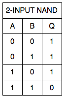
One of the most basic digital circuits is the NAND gate. The output of a NAND gate is a logic 0 when all of its inputs are a logic 1. Truth tables describe how logic gates work. That is to say that they show what the logic gate output is for each combination of inputs. Table E7-1 shows a truth table that describes the operation of a two-input NAND gate. A and B are the two inputs; Q is the output.
QUESTION: What logical operation does a NAND gate perform? (E7A07)
ANSWER: It produces logic 0 at its output only when all inputs are logic 1
QUESTION: What is a truth table? (E7A10)
ANSWER: A list of inputs and corresponding outputs for a digital device
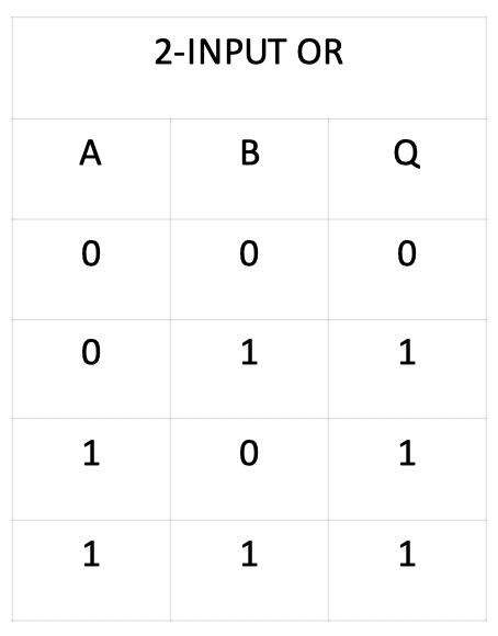
Other types of gates perform different logical functions. OR gates, for example, output a logic 1 if any or all of its inputs are a logic 1. Table E7-2 shows a truth table that describes the logical operation of a two-input OR gate.
QUESTION: What logical operation does an OR gate perform? (E7A08)
ANSWER: It produces logic 1 at its output if any or all inputs are logic 1
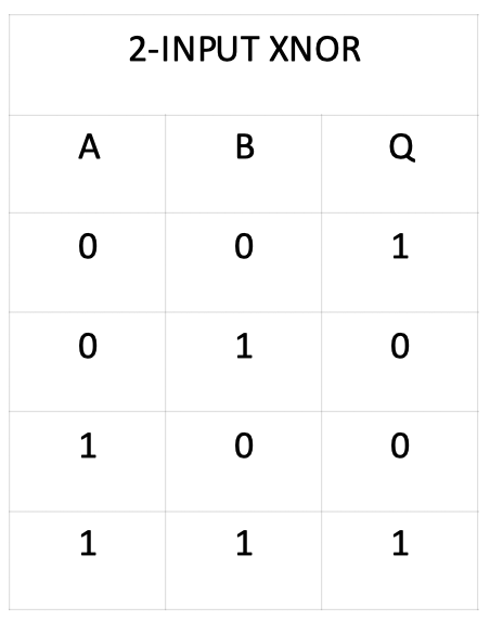
A NOR gate produces exactly the opposite output of an OR gate. That is to say that the output is a logic 0 if any or all of the inputs are a logic 1. An exclusive NOR (XNOR) gate is similar to the NOR gate, except that its output is a logic 0 when its inputs are not all the same value. If all the inputs are a logic 1 or a logic 0, the XNOR gate will output a logic 1 as shown in Table E7-3, which is a truth table for a two-input XNOR gate.
QUESTION: What logical operation is performed by an exclusive NOR gate? (E7A09)
ANSWER: It produces logic 0 at its output if only one input is logic 1
Flip-flops are circuits that are made from combinations of logic gates. By “latching” the state of an input at a particular time, a flip-flop can be said to have memory. A D flip-flop, and its truth table is shown in the figure below.
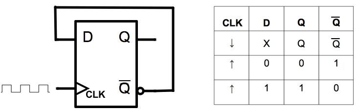
As shown, the output changes only on the rising edge of the clock (CLK) signal. That is to say, when the signal goes from 0 to 1. If D = 1, Q = 1. If D = 0, then Q = 0. The other output, denoted by a bar over the Q, is the inverse of Q.
When a D flip-flop is connected as shown in the figure—with the inverted output connected to the D input—a flip-flop can divide the frequency of a pulse train by 2. You can connect the Q output to a second flip-flop to divide the frequency even further. Consequently, 2 flip-flops are required to divide a signal frequency by 4. By connecting a number of flip-flops together, and resetting the circuit once ten pulses have been input, you can build a decade counter.
QUESTION: Which of the following can divide the frequency of a pulse train by 2? (E7A03)
ANSWER: A flip-flop
QUESTION: How many flip-flops are required to divide a signal frequency by 4? (E7A04)
ANSWER: 2
QUESTION: What is the function of a decade counter? (E7A02)
ANSWER: It produces one output pulse for every 10 input pulses
A flip-flop is a bistable circuit. That means its output is stable in either state—1 or 0. Some circuits—called monostable circuits—are stable in only one state, but not the other. They will switch from one state to the other, but then return to the original state. One such monostable circuit is the monostable multivibrator. A trigger pulse causes the monostable vibrator to switch from a 1 to a 0 (or vice versa), but after a set time, the output of the monostable vibrator will return to its original state. An astable multivibrator is not stable in either state. Its output continuously alternates between two states without an external clock. In other words, it is an oscillator.
QUESTION: Which circuit is bistable? (E7A01)
ANSWER: A flip-flop
QUESTION: What is a characteristic of a monostable multivibrator? (E7A06)
ANSWER: It switches momentarily to the opposite binary state and then returns to its original state after a set time
QUESTION: Which of the following is a circuit that continuously alternates between two states without an external clock? (E7A05)
ANSWER: Astable multivibrator
“A NOR gate produces exactly the opposite output of a NOR gate. ”
I’m pretty sure there’s a typo in there somewhere.
Thanks for catching that. Fixed now.
Extra Class Subelement E7
Who writes these questions for the test ? Its clear that in this case, the developer of the question has no experience working with this logic family, or low voltage dc systems.
Since when is a TTL LOGIC 1 a
‘high voltage?”
Or a TTL LOGIC 0 a “high voltage?”
QUESTION: What type of logic defines “1” as a high voltage? (E7A11)
ANSWER: Positive Logic
QUESTION: What type of logic defines “0” as a high voltage? (E7A12)
ANSWER: Negative logic
I hear you. Unfortunately, I had no input into this year’s question pool.