
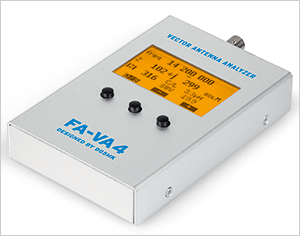
 Since our recent antenna analyzer “bake-off,” I purchased and built a Box73 FA-VA4 antenna analyzer kit. It was fairly easy to assemble, and so far, I’m impressed with it.
When I told my friend, Rick, KA8BMA, that I was going to try to make some measurements comparing the measurements made by the FA-VA4 to the measurements made by the Palstar ZM30, he said he’d bring over his Rig Expert AA-55 ZOOM, and we could compare all three.
My idea was to choose frequencies in the various HF bands, then adjust the antenna tuner to different complex impedances, and then make measurements with each of the analyzers. Here are the measurements we made last night:
| Box73 FA-VA4 | Palstar ZM30 | Rig Expert AA-50 ZOOM | |||||||
| SWR | Z | X | SWR | Z | X | SWR | Z | X | |
| 7100 kHz | 1.05 | 52.4 | -j0.6 | 1.0 | 49 | -j3 | 1.02 | 50.4 | **1 |
| 2.02 | 24.8 | -j2.6 | 2.0 | 24 | +j3 | 2.04 | 24.4 | ||
| 4.27 | 12.9 | -j15.4 | 4.9 | 11 | +j14 | 4.21 | 29.6 | ||
| 14200 kHz | 1.09 | 47.7 | -j3.9 | 1.0 | 46 | +j3 | 1.06 | 50.5 | |
| 2.17 | 49.7 | -j39.2 | 2.1 | 57 | +j40 | 2.1 | 62 | ||
| 5.24 | 150 | +j125 | **2 | 5.1 | 196 |
**1: The RigExpert didn’t indicate the reactance like the FA-VA4 or the ZM30. I wrote down some of the readings, but I’m still puzzling through them.
**2: When I started making this measurement, the ZM30 started acting flakey, as though the batteries were dead. Upon inspection, I found that one of the eight batteries had leaked, so I didn’t make this measurement.
Here are some observations:
- I think that the three meters mostly agree on SWR measurements. The Palstar seemed to be a little off when measuring SWRs around 5.0:1.
- I need to do more research on what the reactive component measurement really means. For example, look at the measurement made by the FA-VA4 at 14200 kHz and 5.0:1 SWR. The measured SWR was 5.24, but the Z is only 150. That doesn’t make sense to me.
- My test method could probably use some improvement. I was relying on adjusting my antenna tuner to generate complex impedances. It would have been better to have test loads with known complex impedances. I Googled “antenna analyzer test loads,” and the only relevant link it came up with is a page showing some load measurements for the SARK-110 Antenna Analyzer. Unfortunately, the page does not describe the loads in detail.
I know this is all kind of half-baked, and I really debated whether or not to post this, but I thought I would anyway to get some feedback. Can any of you explain the discrepancy between the Z and SWR measurements at 5.0:1 SWR?
Also, do any of you have a good suggestion for better test loads to use? I’m going to load up the Palstar with batteries again and try this experiment again once I come up with better test loads.
If I remember correctly, for a complex impedance of 150 + 125j, the magnitude of the impedance would be 195 (according to Pythagoras). That is closer to a 4:1 SWR than 5.24.
KB6NU wrote “Can any of you explain the discrepancy between the Z and SWR measurements at 5.0:1 SWR?”
I think there’s negligible discrepancy. See below.
K6WRU wrote “If I remember correctly, for a complex impedance of 150 + 125j, the magnitude of the impedance would be 195 (according to Pythagoras).”
Yes, to three significant figures.
K6WRU wrote: “That is closer to a 4:1 SWR than 5.24.”
Nope. Assuming that the Z in the table really means R, and that Z = R + jX, then to get SWR from Z (relative to 50 ohms), SWR = [ |Z + 50| + |Z – 50| ]/[ |Z + 50| – |Z – 50| ]. Here the symbols | A | mean absolute value of A.
If Z = 150 + j125 then | Z + 50 | = | 200 + j125 | = sqrt(200^2 + 125^2) = sqrt(55625) = 235.85
while | Z – 50 | = | 100 + j125 | = sqrt(100^2 + 125^2) = sqrt(25625) = 160.08 so this means
SWR = 395.93/75.77 = 5.2254 disagreeing with 5.24 by less than 1%.
The rest of the R, X, and SWR figures for the FA-VA4 and the ZM30 are pretty self-consistent too, but I am bothered by the differences between the two devices, and especially by the fact that for the most part their signs for X disagree.
I don’t think there’s anything wrong with coming up with complex impedances by mis-tuning an antenna tuner, provided you don’t have common mode current on the line running to the analyzer being tested. Some analyzers might behave peculiarly if there were such common mode current. And you don’t know if your readings are right because you don’t know what Z really is, but it will let you test consistency of R, X, and SWR.
I think one of the recent reviews in QST had a sidebar of how to build ‘standard’ loads, including ones with reactance.
Beware of ‘hand capacitance’. All measurements will likely be more accurate if you aren’t actually holding the unit. If it changes a lot, that is a good indication that you are seeing common mode currents.
By my calculation the reflection coefficient is
(X-Z) / (X+Z) = 100 + j125 / 200 + j125 = .640 + j.225
= .6787 at an of angle 19 degrees
The first result is the complex number computed by dividing the two complex numbers and the second is the vector magnitude and angle computed from the complex quotient thanks to Pythagorus.
To get the SWR use the magnitude of the reflection coefficient in the formula
SWR = (1 + |Refl|) / (1 – |Refl|) = 1.6787/.3213 = 5.225
So I concur with the result that the SWR is a bit over 5.2, computing it just a tad bit differently than David.
For more on SWR and Relection Coefficient see RFCafe at http://www.rfcafe.com/references/electrical/vswr.htm
73
I used SimSmith 16.1 (by AE6TY) to chart the load 150, +j150 at 14.2Mhz
SWR is computed to be 5.225