
 I get a lot of email from Keysight, which used to be Agilent, which used to be Hewlett Packard (HP). I like getting this stuff because I like keeping up with what’s going on in the electronics test and measurement world. A lot of it is promotional material, but there’s a lot of good info, too.
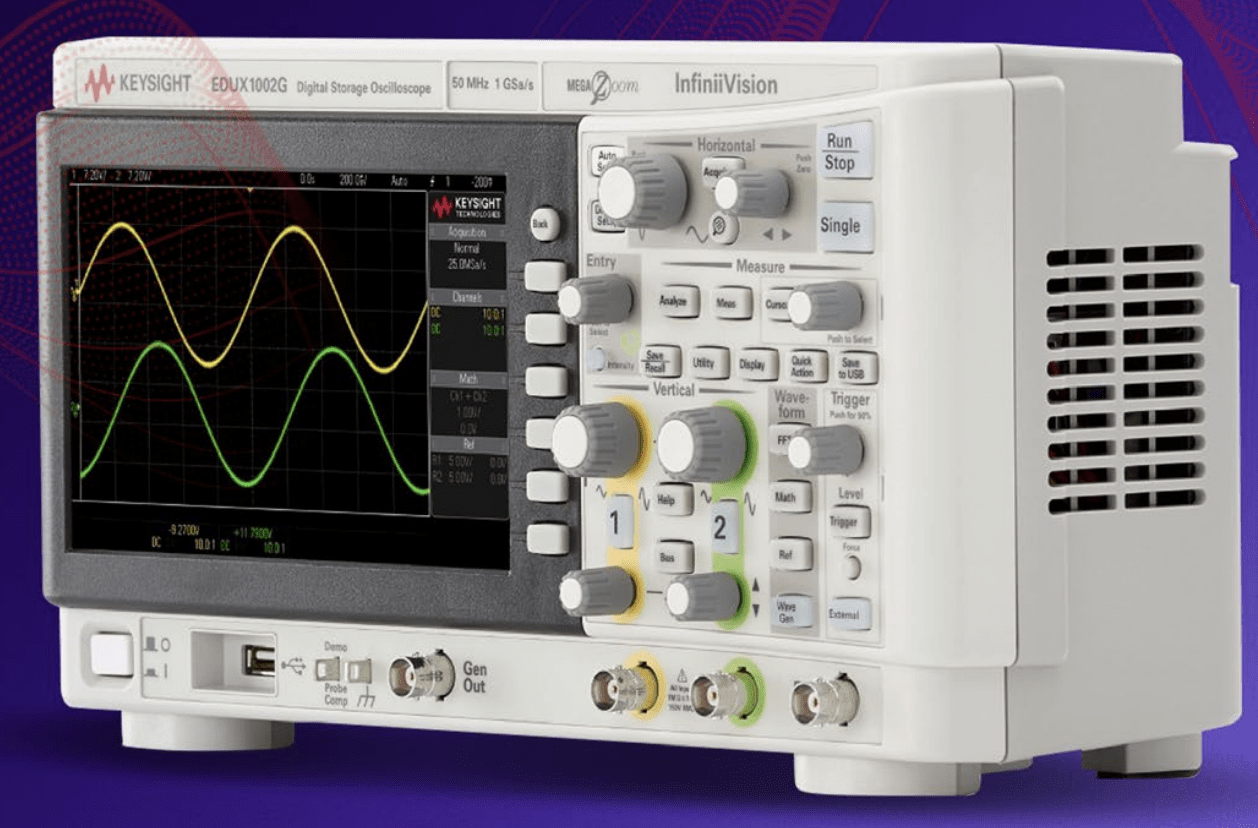
In particular, they’ve been sending me a lot of email about oscilloscopes lately. In late September, they sent me a link to the ebook, “A Step Beyond the Basics: 6 Advanced Oscilloscope Tips.”
In mid-October, they wrote, “Access best practices that help you get the most out of your oscilloscope and enable you to make more accurate measurements. Learn the basics of triggering, how to choose the right probe, proper signal scaling, how to select the right acquisition mode and more. Download the eBook 6 Essential Tips for Getting the Most Out of Your Oscilloscope to begin improving your test results today!”
And, a week ago, their email pointed me towards the Oscilloscope Basics Toolkit. “Access popular tips that have helped hundreds of engineers with triggering, scaling signals, selecting the right bandwidth, removing noise from signals, and more,” they say.
Here’s a tip from 6 Essential Tips for Getting the Most Out of Your Oscilloscope:
Remember Probing Matters
Choose the right oscilloscope probe Probes are used to connect your oscilloscope to your device under test (DUT), and they are crucial for optimizing signal integrity. There are literally hundreds of different oscilloscope probes available, so how do you choose the right one? There’s no single answer because all designs are different. But, here are some different probe characteristics you’ll want to consider before making a decision.
Bandwidth
A probe’s bandwidth describes how high of a frequency the probe is able to pass on to the oscilloscope. Your probes should be at least 3x to 5x faster than the fastest signal you want to see.
Attenuation ratio
Probes have different (sometimes switchable) attenuation ratios that change how the signals are fed into your oscilloscope. A higher attenuation ratio will allow you to look at higher voltages, but it will also make the scope’s internal amplifier noise more pronounced. Low attenuation ratios means you’ll see less scope noise but have more system loading distorting your signal.
Also, the length of the ground lead on the probe can make a big difference when probing high-speed (as in short rise-time) signals. If you use an old-time probe that has a long lead with ground clip, you will end up enclosing the loop that forms around a space that can inject all sorts of noise, and effect the signal display adversely.
If you’ve seen high-speed probes with a tiny square ground probe that is very close to the probe tip, that’s what you need for probing those sorts of signals.
It’s important to note that it isn’t the frequency of the signal that is important, but the rise-time of the signal. You can have a 1 MHz square wave, but with a 1 nanosecond risetime. You will need a several GHz probe and scope to see it properly.