• Skip to primary navigation
  • Skip to main content
  • Skip to primary sidebar
  • Skip to footer

KB6NU's Ham Radio Blog

KB6NU's Ham Radio Blog
  • HOME
  • Study Guides
  • Teach a One-Day Tech Class
  • W8SRC Repeater Guide
  • Advertise
  • Hire Me

oscilloscopes

5 mistakes to avoid when buying a low-cost scope

June 3, 2022 By Dan KB6NU 1 Comment

Keysight has a new application note—5 Common Mistakes to Avoid When Buying a Low-Cost Oscilloscope—that you might want to get if you’re going to buy a scope, or even if you use a scope. This free app note covers the following five topics:

  • selecting an oscilloscope with insufficient bandwidth
  • settling for a USB oscilloscope
  • underestimating usability
  • running the risk of equipment support difficulties
  • focusing solely on specifications

Make sure you have enough bandwidth

A scopes’s bandwidth is the frequency at which the input signal sine waves attenuate by -3 dB (30%) as shown here:
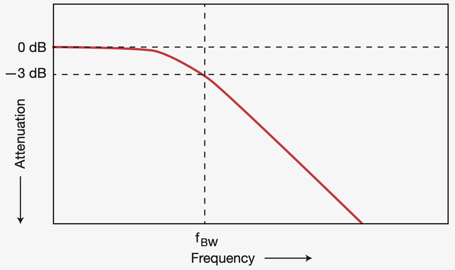
From a practical point of view, what this means is that if you need to measure the amplitude of a 146.96 MHz signal with some accuracy, don’t settle for a 150 MHz scope. The amplitude measurement at that frequency could be up to 30% off. You’ll probably want to purchase a scope with at least 200 MHz bandwidth to make that measurement.

And, when measuring digital signals, having a scope with a high bandwidth is especially important. The reason for this is that while a digital signal may have a relatively low frequency, they contain higher frequency components. Keysight recommends choosing a scope with a bandwidth at least five times the highest clock rate in your system.

Don’t settle for a USB scope

USB scopes are generally cheaper than stand-alone scopes with similar specifications, but remember that you’ll need a computer to provide the user interface. For one thing, it’s not going to be as portable as a stand-alone scope.USB scopes have their place, but probably not for general-purpose use.

Don’t underestimate usability

Even if you only use a scope occasionally, or perhaps especially if you only use a scope occasionally, consider the usability of the scope you intend to buy. Keysight notes that there are several factors contribute to an intuitive and detailed graphical user interface (GUI). These include display quality, display size, resolution, update rate, viewing angle, color versus monochrome, and user-specified display modes such as variable and infinite persistence. Additionally, a multi-language GUI can better contribute to the user’s interaction with the oscilloscope. Ideally, you’d like to be able to play with a scope for a while before buying it.

Make sure that you can get support

Before you plunk down your cash, make sure that you can get support should the scope you buy be DOA or fails after you start using it. Research the support and services offered by the vendor before buying to avoid these  issues. A cheap scope with little or no support is not a bargain.

Don’t focus solely on specifications

Keysight warns, “Specifications do not tell the whole story. You need to dig deeper, read between the lines, and ask questions when researching oscilloscopes to select one that best fits your needs.”

Ask  your friends what kind of scopes they have and if they like using them. You can also head over to the EEVBlog Test Equipment Community Forum. It now has more than a half million posts (!), and test equipment nerds from all over the world hang out there.

This is just a quick review of the Keysight app note. I’d suggest that you download and read the entire thing before buying your next cheap scope.

Filed Under: Test Equipment Tagged With: oscilloscopes

From my Twitter feed: RPi Pico, scope probes, reducing noise in the shack

January 26, 2021 By Dan KB6NU Leave a Comment

digikey's avatar
Digi-Key Electronics  @digikey

@Raspberry_Pi launches their new #PicoBoard featuring their own #silicon. What that means and more >>> dky.bz/3c1KC2P


eevblog's avatar
Dave Jones @eevblog

NEW EEVblog Video! EEVblog #1367 – 5 Types of Oscilloscope Passive Probes COMPARED youtu.be/rzo4Ntxqu1E


mw0ian's avatar
Ian @mw0ian

Replying to @K5PO @_M0JJF and 4 others

Have you guys seen GM3SEK noise video, well worth a watch youtu.be/LSL1h6MJbaI

Filed Under: EMI/RFI, Microcontrollers, Test Equipment Tagged With: oscilloscopes, RaspberryPi

Interesting stuff from the trade magazines: Make your own conductive inkHeathkit, scope fundamentals

December 17, 2020 By Dan KB6NU 1 Comment


How to Brew Your Own Conductive Ink

An engineer gets creative and mixes up a batch of conductive ink to make his son a birthday present.

…read more


Heathkit: An Employee’s Look Back

Heath Company was the largest kit company in the world. Heath designed and put practically every type of electronic product into kit form. Its products, called Heathkits, were exceptionally popular and many are still in use today. Recently, electronic design talked with Chas Gilmore, who was a Heath executive. For those of you who fondly remember Heathkit and miss its products, here’s a look back at this amazing company and the lessons it offers.

…read more


Oscilloscope Fundamentals Poster

Learn how to check the attenuation of your probes, how to check probe compensation, how to connect the probe ground and how to connect the probe tip to the signal you want to measure. Also learn how to avoid pitfalls such as not seeing a signal, aliasing and how to use the built-in help button when all else fails.

…get the poster

Filed Under: Building/Homebrew, Kits, Test Equipment Tagged With: conductive ink, Heathikit, oscilloscopes

2020 Extra Class study guide: E4A – Test equipment: analog and digital instruments; spectrum analyzers; antenna analyzers; oscilloscopes; RF measurements; computer-aided measurements

March 20, 2020 By Dan KB6NU Leave a Comment

An instrument that amateur radio operators frequently use when experimenting or when debugging equipment is the oscilloscope, or simply just “scope.” Oscilloscopes have become more common in amateur radio shacks as prices have fallen, and the technology has moved from analog to digital.
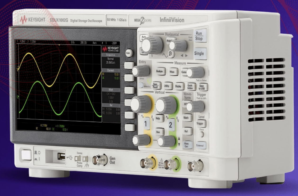

One of the most important oscilloscope specifications is its bandwidth. The bandwidth of an oscilloscope determines the maximum frequency at which the oscilloscope can accurately measure a signal. Several factors determine the highest frequency signal that can be accurately displayed on a digital oscilloscope, including the characteristics of the analog signal processing circuits and the sampling rate of the scope’s analog-to-digital converter.

QUESTION: Which of the following limits the highest frequency signal that can be accurately displayed on a digital oscilloscope? (E4A01)
ANSWER: Sampling rate of the analog-to-digital converter

While digital scopes have many advantages over analog scopes, you have to know how to use them properly. For example, because digital oscilloscopes sample an input signal at discrete time intervals, it is possible to fool them into displaying an incorrect waveform. This phenomenon is called aliasing. If you set the time base too slow, the scope may display a false, jittery version of the input signal.

QUESTION: What is the effect of aliasing on a digital oscilloscope caused by setting the time base too slow? (E4A06)
ANSWER: A false, jittery low-frequency version of the signal is displayed

Oscilloscope probes

When making measurements at RF frequencies, it’s important to connect the probe’s ground connection as close to the location of the measurement as possible. Keeping the signal ground connection as short as possible reduces the noise picked up by the probe and reduces the inductance of the connection, which in turn, makes the measurement more accurate.

QUESTION: Which of the following is good practice when using an oscilloscope probe? (E4A09)
ANSWER: Keep the signal ground connection of the probe as short as possible

Good quality passive oscilloscope probes have an adjustable capacitor in them that needs to be adjusted so that the probe capacitive reactance is at least nine times the scope input capacitive reactance. When this capacitor is adjusted properly, we say that the probe is properly compensated, and the scope will display the waveform with as little distortion as possible.

Most oscilloscopes have a special square-wave output specifically for the purpose of compensating probes. To adjust the compensation, you connect the probe to this output and then adjust the probe until the horizontal portions of the displayed wave are as nearly flat as possible.

QUESTION: How is the compensation of an oscilloscope probe typically adjusted? (E4A04)
ANSWER: A square wave is displayed and the probe is adjusted until the horizontal portions of the displayed wave are as nearly flat as possible

Spectrum analyzers

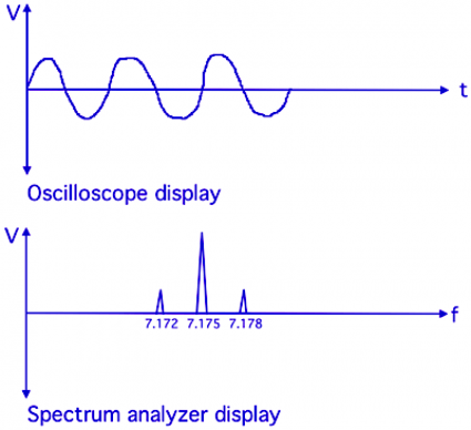
While oscilloscopes display the amplitude of a signal over time, spectrum analyzers display the amplitude of the frequency components of a signal. As shown in the figure below, the horizontal axis of an oscilloscope display represents time, while the horizontal axis of a spectrum analyzer display represents frequency. For both instruments, the vertical axis represent the amplitude of the signal being measured.

Spectrum analyzers are very useful for troubleshooting problems. For example, a spectrum analyzer is used to display spurious signals or intermodulation distortion products generated by an SSB transmitter.

QUESTION: Which of the following parameters does a spectrum analyzer display on the vertical and horizontal axes? (E4A02)
ANSWER: RF amplitude and frequency
QUESTION: Which of the following test instruments is used to display spurious signals and/or intermodulation distortion products generated by an SSB transmitter? (E4A03)
ANSWER: A spectrum analyzer

Antenna analyzers

One of the instruments that I think every amateur radio operator should have (or at least have access to) is the antenna analyzer. Antenna analyzers are versatile instruments that allow amateur radio operators to easily make antenna measurements, as well as other impedance measurements. They can even be used as low power RF signal generators. One of the most common uses for an antenna analyzer is measuring the SWR of an antenna system.

An advantage of using an antenna analyzer compared to an SWR bridge to measure antenna SWR is that antenna analyzers do not need an external RF source. What this means is that you don’t need to connect your transmitter to the antenna to tune it. This is because antenna analyzers have internal RF signal generators.

You can also make related measurements, such as the antenna resonant frequency and feed point impedance with an antenna analyzer. To make these measurements you connect the antenna feed line directly to the analyzer’s connector.

QUESTION: Which of the following measures SWR? (E4A08)
ANSWER: An antenna analyzer

QUESTION: Which of the following is an advantage of using an antenna analyzer compared to an SWR bridge to measure antenna SWR? (E4A07)
ANSWER: Antenna analyzers do not need an external RF source

QUESTION: How should an antenna analyzer be connected when measuring antenna resonance and feed point impedance? (E4A11)
ANSWER: Connect the antenna feed line directly to the analyzer’s connector

Frequency counters, logic analyzers

To measure the frequency of a signal, you use an instrument called a frequency counter. When selecting a frequency counter, an important specification is the maximum frequency. If you want to measure the frequency of a signal whose frequency is higher than the maximum frequency of your counter, you might use a prescaler. A prescaler divides a higher frequency signal so a low-frequency counter can display the input frequency.

QUESTION: What is the purpose of the prescaler function on a frequency counter? (E4A05)
ANSWER: It divides a higher frequency signal so a low-frequency counter can display the input frequency

The proper operation of a digital circuit depends on the output state of many digital ICs at specific times. To ensure that a circuit is working properly, or to troubleshoot a circuit, you may want to use a logic analyzer because it displays multiple digital signal states simultaneously.

QUESTION: Which of the following displays multiple digital signal states simultaneously? (E4A10)
ANSWER: Logic analyzer

Filed Under: 2020 Extra Class Study Guide, Test Equipment Tagged With: antenna analyzers, oscilloscopes, spectrum analyzers

Keysight on Scopes

December 14, 2019 By Dan KB6NU 1 Comment

I get a lot of email from Keysight, which used to be Agilent, which used to be Hewlett Packard (HP). I like getting this stuff because I like keeping up with what’s going on in the electronics test and measurement world. A lot of it is promotional material, but there’s a lot of good info, too.

In particular, they’ve been sending me a lot of email about oscilloscopes lately. In late September, they sent me a link to the ebook, “A Step Beyond the Basics: 6 Advanced Oscilloscope Tips.” 

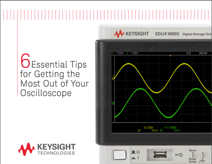
In mid-October, they wrote, “Access best practices that help you get the most out of your oscilloscope and enable you to make more accurate measurements. Learn the basics of triggering, how to choose the right probe, proper signal scaling, how to select the right acquisition mode and more. Download the eBook 6 Essential Tips for Getting the Most Out of Your Oscilloscope to begin improving your test results today!”

And, a week ago, their email pointed me towards the Oscilloscope Basics Toolkit. “Access popular tips that have helped hundreds of engineers with triggering, scaling signals, selecting the right bandwidth, removing noise from signals, and more,” they say.

Here’s a tip from 6 Essential Tips for Getting the Most Out of Your Oscilloscope:

Remember Probing Matters

Choose the right oscilloscope probe Probes are used to connect your oscilloscope to your device under test (DUT), and they are crucial for optimizing signal integrity. There are literally hundreds of different oscilloscope probes available, so how do you choose the right one? There’s no single answer because all designs are different. But, here are some different probe characteristics you’ll want to consider before making a decision.

Bandwidth

A probe’s bandwidth describes how high of a frequency the probe is able to pass on to the oscilloscope. Your probes should be at least 3x to 5x faster than the fastest signal you want to see.

Attenuation ratio

Probes have different (sometimes switchable) attenuation ratios that change how the signals are fed into your oscilloscope. A higher attenuation ratio will allow you to look at higher voltages, but it will also make the scope’s internal amplifier noise more pronounced. Low attenuation ratios means you’ll see less scope noise but have more system loading distorting your signal.

Filed Under: Test Equipment Tagged With: oscilloscopes

App notes and white papers from Rohde & Schwarz

September 14, 2017 By Dan KB6NU 1 Comment

Rohde & Schwarz (R&S) has been in business for 80 years, and is one of the pre-eminent test and measurement companies. As such, they have a lot of expertise that they can share with electronics engineers and amateur radio operators.

Here are some app notes and white papers that you might find interesting:

  1. Introduction to RF Design. R&S says that this is the most dowloaded paper on RF design. This white paper provides insight into how these technologies work, and, after reading this paper you’ll have practical knowledge on the entire process for designing an RF system.

  2. Measuring with Digital Storage Oscilloscopes. This educational note covers the theory and practice of digital storage oscilloscopes based on concrete measurement examples that address authentic everyday tasks. The theoretical portion of this paper begins with an explanation of the basic operating concepts for digital oscilloscopes, followed by a discussion of the most important parameters to be considered when setting up and performing the exercise measurements. The final portion of the theoretical section prepares the reader for the subsequent practical exercises containing detailed measurement tasks. These exercises are intended to demonstrate and reinforce the knowledge gained in the theoretical portion. The exercises build upon one another demonstrating measurement tasks that are encountered frequently by engineers in their daily work.

  3. Spectrum Analyzer Fundamentals – How modern spectrum analyzers are designed and how they work. Spectrum analyzers serve as an essential RF test tool for characterizing signals and making frequency measurements. In this primer you will learn about the basics of spectrum analysis, time and frequency domains, different types of spectrum analyzers, and how to make different types of measurements with a spectrum analyzer.

When you click on the link, you may be asked to give your contact info, but it’s worth it. What I do, when asked to give a company name, is to simply type in my call sign. I’ve never had a Rohde & Schwarz salesman contact me. :)

Filed Under: Gear/Gadgets, Test Equipment Tagged With: oscilloscopes, RF design, Rohde&Schwarz, spectrum analyzers

6 essential tips for getting the most out of your oscilloscope

August 3, 2017 By Dan KB6NU Leave a Comment

The price of oscilloscopes has gotten so low that any amateur radio operator can now afford one. And, these are great scopes, too, packed with lots of features that earlier generations of analog scopes just couldn’t provide.

To  help new scope users take advantage of these features, Keysight, which used to be Agilent, which used to be Hewlett Packard, just published an app note, 6 essential tips for getting the most out of your oscillocope. You have to fill out a form to get this app note, but it’s worth it.

The six tips are:

  1. Get started with basic triggering.
  2. Remember probing matters.
  3. Scale signals correctly.
  4. Use the right acquisition mode.
  5. See more detail using advanced triggering.
  6. Use integrated protocol decoders for advanced serial busses.

Aside from perhaps the last one, these tips will help ham radio operators make better measurements, even if you don’t have a Keysight scope.

Filed Under: Test Equipment Tagged With: Keysight, oscilloscopes

Rigol on RF Basics

November 9, 2016 By Dan KB6NU 1 Comment

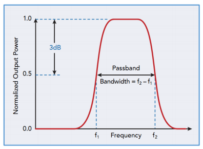
Here’s a white paper on basic RF measurements from Rigol, a manufacturer of oscilloscopes, spectrum analyzers, and signal generators. It does a decent job of explaining topics like the difference between time-domain measurements (that you’d make with an oscilloscope) and frequency-domain measurement (that you’d make with a spectrum analyzer).

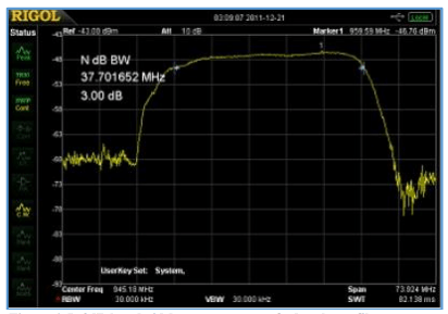
In addition to explaining how scopes and spectrum analzyers work, there are chapters on component tests, transmitter tests, and receiver tests. The third chapter, for example, explains how to use a spectrum analzyer (a Rigol, of course) to measure the bandwidth of filters, connector and cable insertion loss, and antenna VSWR.

screen-shot-2016-11-09-at-2-52-23-pm
An idealized view of a filter’s frequency response.
screen-shot-2016-11-09-at-2-53-10-pm
What you might actually see on a spectrum analyzer when measuring the frequency response of a filter.

I’m a little surprised that they didn’t more information about their latest signal generator, the DG1022Z. At $360, this 25 MHz signal generator looks like a great deal. It offers two output channels that you can program to output a wide variety of waveforms, and modulate those waveforms in many different ways. And, if you don’t find any of the pre-programmed waveforms to your liking, you can create an arbitrary waveform of up to 16 Mbytes long. It also includes a 200 MHz frequency counter.

I’m not sure how much I’d actually use it, but being the test equipment geek that I am, I’m really tempted. I probably should get a spectrum analyzer first, though.

Filed Under: Test Equipment Tagged With: oscilloscopes, signal generator, spectrum analyzer

From the trade magazines: Find cable faults, low-cost scopes, antenna measurements

September 8, 2016 By Dan KB6NU 1 Comment

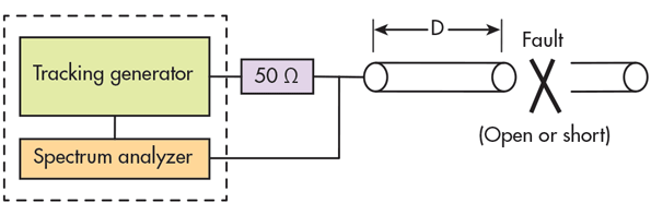
microwaves&rfMethod finds faults in coaxial cables. This article describes how to use a spectrum analyzer instead of a time-domain reflectometer (TDR) to find opens or shorts in a coaxial cable. Basically, using this method, you’re measuring the frequency response of the stub created when a fault occurs. It occurs to me that you could possibly also use an antenna analyzer to make this measurement, depending on where the fault is and the frequency range of the analyzer.

coaxial-cable-fault


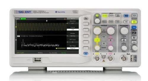
electronic-design10 scopes for under $1500. The scopes discussed in this article range in price from $318 (Siglent SDS1072CML) to $1311 (Keysight DSOX2002A) and bandwidth from 40 MHz to 100 MHz. If you’re thinking about buying a scope for your shack, this article might be a good start. It’s just a start, though. I think it’s missing other good choices, such as the Siglent SDS1152CML that I have. the SDS1152CML has a 150 MHz bandwidth and costs about $450.

My SDS1152DML features a 150 MHz bandwidth for a price around $450.


Getting started with antenna measurements. In amateur radio, we talk a lot about antenna performance, but really have very little in the way of data to back up our discussions. The reason for this is that making antenna measurements isn’t easy. This short blog post gives a little insight into this complex topic.

Filed Under: Antennas, Test Equipment Tagged With: antenna test, cables, oscilloscopes

Primary Sidebar

No Nonsense Technician Class License Study Guide (for tests given between July 2026 and June 2030)

New No Nonsense Technican Class Study Guide now available!

The 2026 version of my Tech Class study guide is now available, and as always, the PDF version is FREE!. The ePub version costs $11.97, and a Kindle version and paperback version will be available on Amazon shortly.

Click here to get all of my "No Nonsense" study guides.

Also available: The CW Geek's Guide to Having Fun with Morse Code

W5SWL.Com
Retevis Ailunce H1 DMR Radio
DXpander: Cobweb antennas, Laser Cutting

You’ve got mail!

Enter your email address below and get an email every time I publish a new post.

Email


I frequently teach classes to help newcomers get their licenses. The next class will take place on Saturday, October 10, 2026 on the University of Michigan campus. Click here for more information.

If you can't make the class, subscribe to the mailing list to be notified of when the next class will be held.

You can always download my free study guide, and if you have any questions about the classes, or amateur radio in general, please feel free to email me directly.

Support KB6NU.Com

Donate $7.30 and get two of these cool stickers. Measuring 4.25-in. W by 2.75-in. H, it's perfect for your car, your shack, or wherever!

Contact me

If you have a question or comment about one of my blog posts, or a question about any of the material in my study guides, or just a question about ham radio in general, you can email me at [email protected].

Blogs You Should Also Read

  • AE5X: A CW-centric blog from Kingswood, Texas
  • K0LWC Blog
  • LA3ZA Ham Radio Blog
  • Little Radios, Big Fun – WB3GCK
  • Mr. Vacuum Tube's Blog
  • Radio Artisan – K3NG
  • The K0NR Weblog
  • VE3WDM's QRP Ham Radio Blog
  • W2LJ’s Blog

Ham Radio Websites

  • Dashtoons – The Hammin' Comedy by Jeff K1NSS

Podcasts

  • ICQ Podcast
  • Linux in the Ham Schack
  • No Nonsense Amateur Radio Podcast
  • Resonant Frequency Amateur Radio Podcast

Recent Comments

  • Bulin 47 AI on ICQPodcast Episode 485 – World Cup Special Event Station
  • Jesse Alexander on What do you think of this artwork for the ham radio EMF Explorer
  • CADProps on My first go at 3D printing not quite a success
  • Dan KB6NU on A Media Guide to Amateur Radio
  • Steve Stroh N8GNJ on A Media Guide to Amateur Radio

Meta

  • Log in
  • Entries feed
  • Comments feed
  • WordPress.org

Footer

Copyright © 2026 Daniel M. Romanchik, KB6NU · Log in