
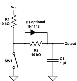
 Last year, I wrote about a problem that a friend of mine was having with a bouncing switch input. I searched the web, found the circuit at right, and proceeded to breadboard it for him. We put the scope on it, and it seemed to work great. A couple of weeks later, however, he called and said that when he tried using it in his math camp class, it didn’t work at all.
A couple of days ago, I got an e-mail from my friend, saying that it was time for math camp and could we take a look at the debounce circuit again. This time, we connected the circuit to the input of a 74LS640 transceiver, as he did last year. Sure enough, it just didn’t seem to switch at all. When I put the scope on it, I found that with the switch closed, the voltage on the output only got down to around 3 V or so.
I’m kind of confused by this. Is the IC input actually sourcing enough current to keep the output at 3 V?
What we ended up doing is wiring up a transistor switch on the debounce circuit output. That works just fine, but seems kind of kludgey to me.
74ls640 inputs have spec’d min input low current of .4ma and .6v. You can’t get .4ma with 10k in the circuit.
This circuit wound work well with CMOS, but not LSTTL or TTL.
So, can I just reduce the value of the resistors to say 1k, realizing, of course, that it’s going to change the RC time constant?
You’d need to change R2 to about 100 ohms to get 0.4V at 4 mA (at 0.6v you have no noise margin). You’re much better off going to a CMOS-input chip. Or–and I know I’m sounding like a broken record–just bite the bullet and go to an SPDT switch and cross-coupled NAND gates, which is pretty much bullet-proof. As a bonus, the kids at math camp will get to figure out how a set-reset latch works.
I was going to do the NAND-gate thing, but I didn’t have any in my junk box.