• Skip to primary navigation
  • Skip to main content
  • Skip to primary sidebar
  • Skip to footer

KB6NU's Ham Radio Blog

KB6NU's Ham Radio Blog
  • HOME
  • Study Guides
  • Teach a One-Day Tech Class
  • W8SRC Repeater Guide
  • Advertise
  • Hire Me

Simple circuit debounces switch

July 16, 2015 By Dan KB6NU 5 Comments

I have a friend runs a math summer camp here in Ann Arbor at the University of Michigan for smart young people.  I’ll write more about this later, but here’s how he describes it:

We build a machine that will allow the user to enter data on a breadboard, using nothing more sophisticated than switches, logic gates, and flip flops, and have the result be a tweet that includes a picture.  Our class of 16 students will each work on a portion of the machine, and at the end we’ll put it all together.

Since its inception, I’ve been the camp’s “electronics consultant.” I loan them a power supply every year, and have, in the past helped them with various electronics questions.

This year, my friend asked me how to debounce a switch. They use a pushbutton switch to clock in data, and as you can imagine, if the switch isn’t debounced properly, they get multiple clocks, which screw up the operation of their machine.

I understand debouncing, but to be honest, I never really had to design a debounce circuit. So, I did a little Googling and found, “A Guide to Debouncing” by Jack G. Ganssle. Ganssle. This 22-page monograph really gets into the theory of why switches bounce and describes several different ways to debounce a switch. One of the simplest ways to do this—and probably the most appropriate method for this project—is a simple RC circuit:

rc-debounce-ckt

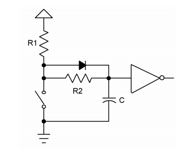
Basically, the way this works is that C charges to VCC, and when you throw the switch to take the logic circuit input low, C discharges. You set the values of C and R2 such that the time constant is at least as long as the time during which the switch bounces.  Ganssle describes how to do this, and he’s even made some measurements on how much time you need for the switch to quit bouncing.

The diode in the circuit is optional. Its function is to speed up the capacitor charging once the switch is released.

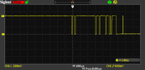
I dug though my junk box and found all the components that I needed to breadboard the circuit, then used my fancy, new digital scope to observe both the bouncy switch input and the debounced circuit output. Here is the bouncy switch:

SDS00001


And here is the debounced waveform:

SDS00002

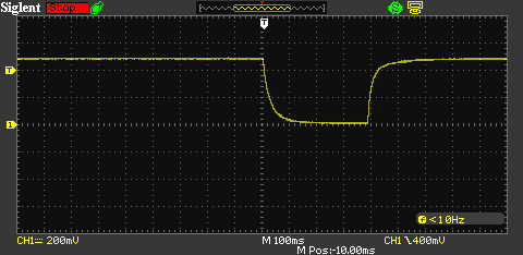
I know that this is a very simple circuit, and that I really shouldn’t be surprised that it works, but I like it when simple things work. The result here is that my friend’s summer camp will have a stable clock input, and the circuit is something that he can easily explain to the kids. It should be as educational for them as it was for me.

Related posts:

  1. Not enough bounce
  2. Deciphering schematics like solving a puzzle
  3. 2020 Extra Class study guide: E7A – Digital circuits: digital circuit principles and logic circuits; classes of logic elements; positive and negative logic; frequency dividers; truth tables
  4. Unit Conversions Made Simple

Filed Under: Building/Homebrew, Digital Logic

Reader Interactions

Comments

  1. Bob, KG6AF says

    July 17, 2015 at 6:57 pm

    I’d go with the S/R flip-flop debouncer, which Ganssle also describes. It needs an SPDT switch, but you don’t have to monkey with choosing the correct Rs and C.

    As a digital designer, I get nervous whenever I look at a digital schematic and see capacitors on signal lines. It’s rarely a good sign. It’s not that there are no good reasons to use them, it’s just that there are so many bad reasons.

    Reply
    • Dan KB6NU says

      July 17, 2015 at 8:28 pm

      In general, I agree with you, Bob, but for this particular application, I think the RC circuit will work and be educational as well.

      Reply
      • Bob, KG6AF says

        July 24, 2015 at 12:08 am

        I agree. I suspect that there are a lot of folks out there who don’t know that you have to debounce a switch in the first place, so this is a very useful project.

        Reply
  2. Ross Herbert says

    October 26, 2020 at 10:47 pm

    Unless my logic is wrong the output of the inverter should be low when the NO switch is at rest. The output will go high when the switch is pressed. This is opposite to the scope trace.

    Reply
  3. M. Simon says

    October 27, 2023 at 7:54 am

    A simple zero debounce delay debouncer.
    https://spacetimepro.blogspot.com/2023/09/switch-debouncer.html

    Reply

Leave a Reply Cancel reply

Your email address will not be published. Required fields are marked *

This site uses Akismet to reduce spam. Learn how your comment data is processed.

Primary Sidebar

No Nonsense Technician Class License Study Guide (for tests given between July 2026 and June 2030)

New No Nonsense Technican Class Study Guide now available!

The 2026 version of my Tech Class study guide is now available, and as always, the PDF version is FREE!. The ePub version costs $9.97, and a Kindle version and paperback version will be available on Amazon shortly.

Click here to get all of my "No Nonsense" study guides.

Also available: The CW Geek's Guide to Having Fun with Morse Code

W5SWL.Com
Retevis Ailunce H1 DMR Radio
DXpander: Cobweb antennas, Laser Cutting

You’ve got mail!

Enter your email address below and get an email every time I publish a new post.

Email


I frequently teach classes to help newcomers get their licenses. The next class will take place on Saturday, February 7, 2026 on the University of Michigan campus. Click here for more information.

If you can't make the class, subscribe to the mailing list to be notified of when the next class will be held.

You can always download my free study guide, and if you have any questions about the classes, or amateur radio in general, please feel free to email me directly.

Support KB6NU.Com

Donate $7.30 and get two of these cool stickers. Measuring 4.25-in. W by 2.75-in. H, it's perfect for your car, your shack, or wherever!

Contact me

If you have a question or comment about one of my blog posts, or a question about any of the material in my study guides, or just a question about ham radio in general, you can email me at [email protected].

Blogs You Should Also Read

  • AE5X: A CW-centric blog from Kingswood, Texas
  • K0LWC Blog
  • LA3ZA Ham Radio Blog
  • Little Radios, Big Fun – WB3GCK
  • Mr. Vacuum Tube's Blog
  • Radio Artisan – K3NG
  • The K0NR Weblog
  • VE3WDM's QRP Ham Radio Blog
  • W2LJ’s Blog

Ham Radio Websites

  • Dashtoons – The Hammin' Comedy by Jeff K1NSS

Podcasts

  • ICQ Podcast
  • Linux in the Ham Schack
  • No Nonsense Amateur Radio Podcast
  • Resonant Frequency Amateur Radio Podcast

Recent Comments

  • Skip K4EAK on Button, button. Who’s got the button?
  • Ed K8MEJ on Is anyone running for the board this year in the Great Lakes Division?
  • Skip Behnke on 2020 Extra Class study guide: E9F – Transmission lines: characteristics of open and shorted feed lines; coax versus open-wire; velocity factor; electrical length; coaxial cable dielectrics
  • Mike on Map your contest QSOs
  • Phillip Cardwell on J-Poles

Meta

  • Log in
  • Entries feed
  • Comments feed
  • WordPress.org

Footer

Copyright © 2026 Daniel M. Romanchik, KB6NU · Log in