
On July 1, 2020, this post will be obsolete. See the corresponding post from my 2020 version of No Nonsense Extra Class License Study Guide.
E7H – Oscillators and signal sources: types of oscillators; synthesizers and phase-locked loops; direct digital synthesizers; stabilizing thermal drift; microphonics; high accuracy oscillators
Oscillator circuits are one of the basic building blocks of amateur radio equipment. Oscillator circuits are not only used to generate the signals we transmit. They are also an integral part of receivers, such as the superheterodyne receiver.
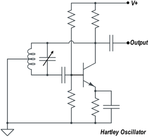
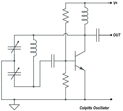
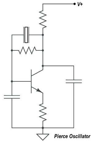
You can think of an oscillator as an amplifier with a tuned circuit at the input. This tuned circuit might be an LC circuit or a crystal. The values of the components in the tuned circuit determine the output frequency of the oscillator. There are three types of oscillator circuits commonly used in Amateur Radio equipment – Colpitts, Hartley and Pierce. (E7H01) Colpitts and Hartley oscillator circuits are commonly used in VFOs. (E7H06)
For a circuit to oscillate, it must have positive feedback. In a Hartley oscillator (shown in the figure below), positive feedback is supplied through a tapped coil. (E7H03)
In a Colpitts oscillator, positive feedback is supplied through a capacitive divider. (E7H04)
In a Pierce oscillator, positive feedback is supplied through a quartz crystal. (E7H05) To ensure that a crystal oscillator provides the frequency specified by the crystal manufacturer, you must provide the crystal with a specified parallel capacitance. (E7H12) NPO capacitors are components that can be used to reduce thermal drift in crystal oscillators. (E7H08)
One problem that oscillators sometimes have is called microphonics. Changes in oscillator frequency due to mechanical vibration describes a microphonic. (E7H02) An oscillator’s microphonic responses can be reduced by mechanically isolating the oscillator from its enclosure. (EH707)
Digital frequency synthesizers
Most modern amateur radio transceivers use digital frequency synthesizers instead of analog oscillators to generate RF signals. One reason for this is that they are much more stable than analog oscillators. The two main types of digital frequency synthesizers are the direct digital synthesizer and the phase-locked loop synthesizer.
A direct digital synthesizer is the type of frequency synthesizer circuit that uses a phase accumulator, lookup table, digital to analog converter and a low-pass anti-alias filter. (E7H09) The information contained in the lookup table of a direct digital frequency synthesizer is the amplitude values that represent a sine-wave output. (E7H10)
Another type of frequency synthesizer that’s popular are those that use a phase-locked loop. A phase-locked loop circuit is an electronic servo loop consisting of a phase detector, a low-pass filter, a voltage-controlled oscillator, and a stable reference oscillator. (E7H14) Frequency synthesis, FM demodulation are two functions that can be performed by a phase-locked loop. (E7H15)
Both direct digital synthesizers and phase-locked loop synthesizers have issues with spectral purity. The major spectral impurity components of direct digital synthesizers are spurious signals at discrete frequencies. (E7H11)
Because frequency multipliers are often used for generating RF signals at microwave frequencies, it is very important that the oscillators used in microwave transmitters are accurate and stable. Any inaccuracy or instability will be multiplied along with the desired frequency. All of these choices are correct when talking about techniques for providing highly accurate and stable oscillators needed for microwave transmission and reception: (E7H13)
- Use a GPS signal reference
- Use a rubidium stabilized reference oscillator
- Use a temperature-controlled high Q dielectric resonator