
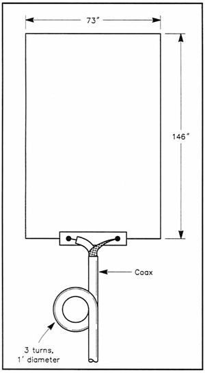
It takes me forever to complete some projects. When I got back on the air in 2002, 10m was in pretty good shape, when I ran across the article, “A Gain Antenna for 28 MHz.” It seemed simple enough to build, and I even went so far as to purchase and cut to length two pieces of PVC pipe to support the antenna. Well, time went by, and I never got around to finishing the antenna before the sunspot cycle went south on me.
This sunspot cycle has been notably lackluster, at least up until about a month or so ago. The ten-meter band was rarely open, so I wasn’t really motivated to finish and put up this antenna.
About a month ago, though, noting the more frequent band openings, I finally decided to finish the antenna. I cut the wire and attached it to a Budwig center insulator. Then, I left it laying on the floor of my shack.
Well, today, with the temperatures in the 40s, was the perfect day to get it in the air. I flung a tennis ball over a tree branch in my backyard and hauled it up. I’m finally on 10m with an antenna that should work better than my 30m dipole!
The SWR is 1:1 down in the CW portion of the band and still only 1.5:1 at 28.500 MHz. Not bad, I’d say.
Unfortunately, there wasn’t a whole lot of activity on this afternoon around 3:00 pm when I finally got it in the air. I did manage to work HH2/HB9AMO, though, and a station in UT and one in the Virgin Islands heard me calling CQ and reported as such on ReverseBeacon.Net. Bring on the skip!
Good antenna. I wonder if it would works as well if it is wider than it is tall? On 20 meters that would probably be a better choice since dimensions are essentially double those of 10 meters. Food for thought along with floppy PVC tubing.
The reason the dimensions are as they are is so the feedpoint impedance is 50 ohms. Changing the dimensions will change the feedpoint impedance. Think about a folded dipole. In a folded dipole, you have two, half-wave elements very close to one another, with a feedpoint impedance of 300 ohms.
73!
BUILT WITH A VERTICAL ANTENNA LOOP HORIZONTAL POLARIZATION IS INCREDIBLE INCOME, WITH LOW POWERS, SHE REALLY MAKES A DIFFERENCE.
py2fb/qrp
this antenna was described way way back in an arrl hand book… been using it for decades
It’s a great antenna, isn’t it? It’s simple, yet effective.
This a Amazing Antenna.
I’m using 3 el Recta Loop for 27.555..
care to share the blueprint…thanks in advance
I’m building one! Sounds very good! I’m thinking of using a 1:1 balun since I have one on hand. Any thoughts?
I don’t think I’d use one, if I were you. Baluns are meant to balance the currents in the two elements of a dipole antenna. That concept doesn’t really translate to a loop antenna.
Baluns (balanced to unbalanced) are used to transform a balanced load to an unbalanced feed line such as coax. It can also choke off unwanted RF currents flowing down the shield of a coax line. This antenna is already balanced since it is center fed.
SOme people have no idea that antennas are based on theory, and loops are great, the balun in the coax is not to balance the antenna, loops are self-balancing, it is to eliminate rf on the shield of the coax in this configuration, not balance the loop
Hi
Im a HF listener from Israel. this antenna looks interesting and i have started building it.
Have several questions sorry for the long post:
I have started to build this antenna and due to a silly mistake i have divided the antenna wire length to 4 equal segments (a perfect square).
How would it affect the reception (if at all).
Looking further to transmitting (I’m still in the process of certification), how would it affect the antenna impedance?
If the antenna impedance shall be changed – can i make a “balloon” from a RG58 coax to match it or do i need to buy one?
How do i calculate the antenna impedance, taking into consideration that all 4 corners are even in length ?
May i incorporate another loop inside this one to receive VHF *(i.e. 2 M) W/O affecting the 10M performance?
thanks very much
Changing the shape will affect the impedance. What I would suggest if you don’t have more wire is to simply splice the pieces together. That way, you won’t need a balun at all.
As far as incorporating a loop within a loop, I don’t really know. I was thinking about trying it, though.
If you are just listening then do not worry about the equal sides or the balun. The impedance will be slightly higher with the equal sides, but when listening you most likely won’t notice any degradation in your received signals. The balun using the coax is also not needed as that is for taking RF off of the shield of the cable that would degrade the directivity of the antenna by combining the radiated waves from the cable and the antenna. The additional loops can be added, but the resonance of both loops will not be of the calculated lengths for the small antenna will act like a shorted stub for the larger antenna and visa-versa. It may still be sufficient on both bands to work well enough for receiving purposes having both antennas on a single coax cable. Try it.
I’m building one as I write but I have a question about the “three turns” of coax. Is the coil one(1) inch in diameter or one(1) foot diameter? //
1 foot. It’s doubtful that you could coil any except the smallest coax into a 1-in. diameter. On the other hand, a 1-ft. diameter coil seems bigger than normal. Split the difference and make the coil 6-8 inches in diameter. :)
FM Dan – and thank you for your prompt response…. I’ll get busy!!! Steve //
Thanks for the info. So the antenna is oriented as shown in the pic with the 73″ horizontal piece pulled up some height above ground? Have you ever done a horizontal loop?
No, I haven’t tried it horizontally, but I don’t know why it wouldn’t work that way.
I just assembled a installed a delta loop for ten meters..I didnt have any spare coax laying around and did not feel like waiting to get it shipped so I went ahead and made my own ladder line out of some spare 12 thhn wire I had in the basement.
I made the spacers out of some 1″ dowels I had . made them 7-1/2 half inches long and put the holes for the wire at 6 inches. After all that I hoisted it up in my tree in the back yard. Top of the loop is about 35 feet. The loop loads up 10-17 meters no problem with my MFJ 949D tuner. made some great contacts into Europe and Scandinavia. I will probably go ahead and make it lke you have yours configured. Meanwhile 73 to everyone !
Very cool, William!
I am looking for a 10-meter square loop antenna. Any suggestions?
Why square?
Having asked that, you could make any 10-meter loop of wire into a square configuration, but I don’t think that the feedpoint impedance will be 50 ohms. Cushcraft makes what they call the Sqalo antenna, but they’re kind of pricey – $250 for a 10-meter version. If you take a look at the photo of one, you’ll seen that there’s some kind of impedance matching network at the feedpoint.
I am thinking the coax is RG 58 and you can make the loop with it at one inch
I’d like to suspend a 6-meter loop for 50.200 MHz, inside the 10-meter loop, if you think it would work. Could you provide the dimensions based on your calculations for the 10-Meter loop? It might be fun to try. Thanks Steve W4SB… //
I was going to try something similar, so I do think it might work. Since the total loop length is 6m, the dimensions for the horizontal portions of the loop should be approximately 1 meter, while the vertical portions should be approximately 2 meters.
This does sound interesting. I am traveling work work so i spend a lot of times in a hotel room. I run QRP on 10, and use a 1/4 wave dipole inside the room on the ceiling. works fair.
My question is do you think this may work mounting it flat that low or would it be more of a decoration above me.
In my siruation I can’t make it vertically. but horizontally is a go. What is your opinion?
It should work. Give it a try!
Thanks Dan for the ideas on antennas. In a book by Steve Cerwin, WA5FRF, entitled “Radio Propagation and Antennas”, on page 141, he shares an NEC graphic depicting the change in feed-point impedance when the height to width ratio of the loop is changed. The feed-point impedance changes quite remarkably as the aspect ratio of the loop is modified. I found it quite interesting that when the ratio is 2:1 (loop is twice as high as it is wide), the bottom side of this loop, fed in the center, will yield a feed-point impedance of approximately 50 ohms with a respectable gain of 4.5 dBi. It’s exactly supporting the antenna for 10 meters you offered above. Easy to build, needs only one rope for support, and has gain. Take a look at Steve’s book. He has done a very good “non-mathmatical” job of explaining a lot of antenna and propagational theory in a practical way. Thanks for all you do for ham radio Dan…73 de W4JF (Joe)
Hello, do you have any pictures of a completed version of this antenna? Thanks.
No, I don’t have any actual photos, but it looks almost exactly like the drawing.
Based on the dimensions and yes I understand the objective per the 50 ohm match. Per this design, do you have the formula used to use this on other bands? or at least higher up on 10m?
I don’t have a chart with the dimensions for other bands, but the two vertical sections and 1/3 wavelength long and the two horizontal sections are 1/6 wavelength long.