
• Skip to primary navigation
  • Skip to main content
  • Skip to primary sidebar
  • Skip to footer

KB6NU's Ham Radio Blog

KB6NU's Ham Radio Blog
  • HOME
  • Study Guides
  • Teach a One-Day Tech Class
  • W8SRC Repeater Guide
  • Advertise
  • Hire Me

Antennas

The Slinky Antenna

May 18, 2003 By Dan KB6NU 15 Comments

I used to work for Jon Titus, KZ1G, when he was editor of Test&Measurement World magazine. In addition to being a fine editor, he is the developer of the Mark-8 Minicomputer, which some folks consider to be the first personal computer. He published an article on how to build this computer in the July 1974 issue of Radio-Electronics.

In addition to being a personal computer pioneer, he’s also been a ham radio operator for a long time. At one point, he acquired the patent from the inventor of the Slinky antenna and sold them for a number of years. The patent has since expired, but he still owns the trademark.

I found out about this one day while we were talking about antennas. He was so enthusiastic about the antenna, I said that I’d have to try it for myself. He said that even though he no longer sold the antenna, he thought he still had some of the parts, and that he’d look for them when he got home. A couple weeks later, a package arrived containing two Slinkies, a center insulator, two aluminum clips, and an instruction sheet.

The Slinky dipole antenna, for those unfamiliar with it, uses two Slinky coils instead of wire for the dipole elements. The Slinkies used for the antenna have a bigger diameter than the Slinky toys. This allows you to use fewer turns than if you used the Slinky toys for your antenna. Jon had these coils specially made.

When stretched, the Slinkies form are helical coils. To keep the coils horizontal, you must string a rope through the Slinkies and attach the rope to the antenna suports. I use a pulley attached to my house as one antenna support and a tree branch for the other.

The length of a dipole made with Slinkies as the elements is much shorter than a dipole made simply of wire. In fact, the instructions recommmend that the overall length of the antenna be no more than a quarter wavelength and can be much shorter. You tune the antenna by shorting out a number of coil windings with the aluminum clips.

A Long Time Coming
I hate to admit this, but it took me years to actually build the antenna. What finally prompted me to do so was that our club set up a multi-op station to work the Michigan QSO Party. I figured that the Slinky would be easy to set up and tune, and beause it’s a short dipole, could fit in a small space if need be.

As it turned out, it was all of that. At first, we decided not to use the antenna. Our host had erected an 80m bazooka antenna, and one of the other guys had brought a multi-band trap dipole. Because we only planned to operate two transmitters, we figured that we’d use a tuner to load up the bazooka on 40m, and use the trap dipole on the higher bands.

As it turned out, however, we weren’t able to get a good match on 40. So, we scrambled and put up the Slinky, tuning it to 40m.

At first, we thought there was something wrong with the antenna. While Tom and I struggled to erect the thing, Sam was reading the SWR with my antenna analyzer. At one point, Sam said, “The SWR looks pretty good now,but it’s jumping around.” I asked myself what could be wrong– bad solder joints, bad coax?

I went downstairs to see for myself. The measurements were indeed jumping around, but as I puzzled over this, I soon noticed that the SWR jumped whenever the operator of station #1 began sending. What we were reading was not a high SWR, but rather RF being emitted by the first transmitter!

After solving that little teaser, we hooked it up to the Drake Twins we were using on 40, and it worked solidly, if not spectacularly for the rest of the day. When we decided to pack it in, it took us only 15 minutes to take it down.

Last weekend, I strung it between two trees in my front yard so that a friend and I could work two transmitters in the Fists Spring Sprint. Despite being only 15 feet off the ground, it worked well despite poor band conditions.

The next day, I took it down and put it up in my backyard, tuning it to 30m instead of 40m. I’m working almost everything I can hear, and getting good signal reports in the process.

One thing I notice about the antenna is that it doesn’t like being wet. The SWR goes from about 1.1:1 to almost 1.4:1 when it rains. Maybe that has something to do with the supporting rope.

Despite it working so well on 30, I think I’m going to put it back on 40. There just isn’t enough activity on 30 for my taste. More about 30m later.

Links
Here are some links describing the Slinky Antenna and variations on the theme:
  • The Helitrix Antenna
  • My home-built Slinky dipole antenna for the 10 – 80 meter bands
  • Slinky and Loaded Beverages
  • Beverages: How Short Can They Be?

Filed Under: Antennas

J-Poles

November 20, 2002 By Dan KB6NU 3 Comments

My biking and ham radio buddy, Mark, came over Monday evening. We had three objectives:

  1. measure the SWR of J-pole I built a couple of months ago,
  2. measure the SWR of the 2m/440 antenna I just purchased from Purchase Radio, and
  3. build a 2m J-pole for Mark

To measure the SWR, Mark brought over his MFJ 259 Antenna Analyzer. In some ways, it’s much nicer than the Autek Analyzer that I have. For one thing the display is much more informative. The Autek display consists of simply a five-digit numeric display, capable of displaying only one parameter at a time. The MFJ is a full alpha-numeric display and displays the test frequency, the measured SWR, and some other information simultaneously.

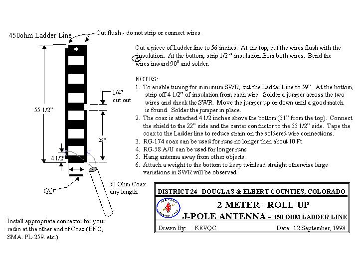
Here are the plans for the 2m j-pole antenna that we built.

The MFJ analyzer’s frequency range is also much greater. It covers the 2m and 440 MHz bands, while the Autek only goes up to 32 MHz. Mark doesn’t think it’s very accurate at 440, though.

The first thing we did was measure the SWR of the J-pole I’d built. I’ve been very happy with the antenna, so I was a little surprised that the first reading was slightly over 2.0. I did have it hanging very near to a fairly massive new barbecue grill we have, so surmising that the grill was detuning the antenna, I moved it away from the grill and the SWR did go down to about 1.5. Respectable in my opinion.

Next, we measured the SWR of the dual-band antenna. This antenna is a 5/8 wavelength antenna that I had mounted on a mast. Its SWR measured about 1.5 near the ARROW 2m repeater frequency of 14.96- MHz. I was happy with that, so we moved on to the antenna construction.

We built the J-pole from plans I found on the Net (shown above). You can build J-poles from 300 ohm twinlead, 450 ohm ladder line, and 1/2-in. copper pipe. The dimensions for each of these versions is slightly different, as the velocity factors are all different.

We opted to build ours with the ladder line because we each already had a hunk of it and it’s much easier to carve up some ladder line than solder up copper pipe. It’s not as sturdy, but it’s certainly sturdier than 300 ohm twinlead.

When I built mine, I did not have an SWR meter to tune the antenna with. So, I just built it to the recommended dimensions, and as mentioned earlier, it turned out to work pretty well. Since we had the analyzer when we built Mark’s we played around with the tuning stub, and it appears that he was able to get a slightly better match than I was.

Overall, it was mission accomplished.

Filed Under: Antennas

A Tip For Using the Autek VA1

November 3, 2002 By Dan KB6NU 1 Comment

In the last entry, I mentioned not being able to tune the antenna for an SWR lower than 1.5:1. Well, it struck me last night as I was falling asleep why this was so. When calculating the SWR, the Autek VA1 assumes that you’re using a 50 ohm feedline. D’oh!

Fortunately, the Autek allows you to change that setting. You can program it to a number of different values from 25 ohms up to 450 ohms. Now, I’ll just have to remember to do that when working with RG-59 or ladder line or whatnot.

Filed Under: Antennas, Gear/Gadgets

Fun With Antennas

November 2, 2002 By Dan KB6NU 1 Comment

I got back on the shortwave bands in August, putting up a 20m dipole. While 20m is fun, I’ve wanted to try out some of the other bands, too. When I was a kid, I used to work 40m a lot, especially late at night. So, I decided to put up a 40m dipole.

I’m lucky in that I have a number of trees to use as an antenna support. While there’s not quite enough space to string an 80m dipole, I guesstimated that a 40m antenna would fit quite nicely.

So, I mail-ordered a bunch of stuff from RadioWorks. The stuff was very nice quality, but I was a little miffed that some of the prices were higher than advertised. I understand that prices can change, but they really should make an effort to update the ads they run in QST and other magazines. It looks to me like they haven’t been updated for more than a year.

At any rate, I got all the parts, and in rummaging through my junk boxes came across a 1:1 balun that someone had given me. I built the dipole using that balun instead of the RadioWorks balun that I’d just purchased. The antenna wire I bought is that fancy, flexible stuff. As advertised, it was very easy to work with, and looks to be quite strong, too. I also put together a 100′ RG 59 cable.

So, Saturday afternoon I get out into the backyard and string it up. Using the Autek VA1 antenna analyzer, I adjust the length for the lowest SWR I can manage. Oddly, it doesn’t seem as though I can get it much lower than about 1.5:1, but that’s OK. It should still work. (More about this later.)

Finally, I get the thing up in the air, and hurry down to the shack to give it the smoke test. I check the SWR again with the Autek, and it looks pretty good. I connect it to my rig–an Icom IC-735–and tune around for a clear frequency. Finally, I put the power to it, and adjust the internal SWR meter.

Wow. The SWR looks even better than it did with the Autek. I send out a few Vs, and then my wife comes rushing downstairs. “”You’re coming in loud and clear,”” she says, “”over the computer speakers! AND you’re making the garage door go up and down, to boot!””

Yipes. I didn’t have this problem with the 20m dipole at all, and I thought a balun was supposed to help reduce RFI.

At this point, it was almost dinnertime, so I just pulled the plug on the rig and decided to sleep on things. It’s too bad, too, because I had wanted to make a few contacts in the CW Sweepstakes Contest. Oh well.

Filed Under: Antennas, EMI/RFI Tagged With: dipole, rfi

  • « Go to Previous Page
  • Page 1
  • Interim pages omitted …
  • Page 34
  • Page 35
  • Page 36

Primary Sidebar

No Nonsense Technician Class License Study Guide (for tests given between July 2026 and June 2030)

New No Nonsense Technican Class Study Guide now available!

The 2026 version of my Tech Class study guide is now available, and as always, the PDF version is FREE!. The ePub version costs $11.97, and a Kindle version and paperback version will be available on Amazon shortly.

Click here to get all of my "No Nonsense" study guides.

Also available: The CW Geek's Guide to Having Fun with Morse Code

W5SWL.Com
Retevis Ailunce H1 DMR Radio
DXpander: Cobweb antennas, Laser Cutting

You’ve got mail!

Enter your email address below and get an email every time I publish a new post.

Email


I frequently teach classes to help newcomers get their licenses. The next class will take place on Saturday, October 10, 2026 on the University of Michigan campus. Click here for more information.

If you can't make the class, subscribe to the mailing list to be notified of when the next class will be held.

You can always download my free study guide, and if you have any questions about the classes, or amateur radio in general, please feel free to email me directly.

Support KB6NU.Com

Donate $7.30 and get two of these cool stickers. Measuring 4.25-in. W by 2.75-in. H, it's perfect for your car, your shack, or wherever!

Contact me

If you have a question or comment about one of my blog posts, or a question about any of the material in my study guides, or just a question about ham radio in general, you can email me at [email protected].

Blogs You Should Also Read

  • AE5X: A CW-centric blog from Kingswood, Texas
  • K0LWC Blog
  • LA3ZA Ham Radio Blog
  • Little Radios, Big Fun – WB3GCK
  • Mr. Vacuum Tube's Blog
  • Radio Artisan – K3NG
  • The K0NR Weblog
  • VE3WDM's QRP Ham Radio Blog
  • W2LJ’s Blog

Ham Radio Websites

  • Dashtoons – The Hammin' Comedy by Jeff K1NSS

Podcasts

  • ICQ Podcast
  • Linux in the Ham Schack
  • No Nonsense Amateur Radio Podcast
  • Resonant Frequency Amateur Radio Podcast

Recent Comments

  • Dan KB6NU on 2015 General Class study guide: Section G2E – Digital operating: procedures, procedural signals, and common abbreviations
  • Jimi on 2015 General Class study guide: Section G2E – Digital operating: procedures, procedural signals, and common abbreviations
  • Ali on Some Good Advice on Learning Morse Code
  • mike on Instant Character Recognition is the key to CW speed
  • Matt W1CDN on A completely different picture of Wayne Green, W2NSD (SK)

Meta

  • Log in
  • Entries feed
  • Comments feed
  • WordPress.org

Footer

Copyright © 2026 Daniel M. Romanchik, KB6NU · Log in