
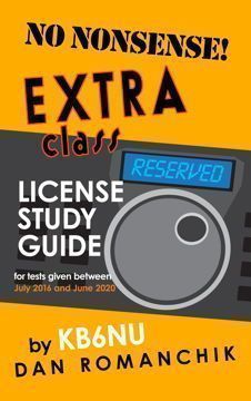
Jeff, K1NSS, and I have put our heads together and come up with covers for the next round of study guides. What do you all think?

Jeff, K1NSS, and I have put our heads together and come up with covers for the next round of study guides. What do you all think?
Here’s chapter 3 of the next edition of my No Nonsense Technician Class License Study Guide. As always, comments welcome!
Radio waves are what amateur radio is all about. Amateur radio operators generate them and send them off into space. And, on the other side, we capture them and demodulate them.
Radio waves are also called electromagnetic waves because they consist of both an electric wave and a magnetic wave. The two waves are at right angles to one another, and as the wave travels through space, energy gets swapped between the electric and magnetic waves. This is what propels them through space.
QUESTION: What type of wave carries radio signals between transmitting and receiving stations? (T3A07)
ANSWER: Electromagnetic
QUESTION: A radio wave is made up of what type of energy? (T5C07)
ANSWER: Electromagnetic
QUESTION: What are the two components of a radio wave? (T3B03)
ANSWER: Electric and magnetic fields
One important characteristic of a radio wave is its frequency, or the number of cycles that it goes through per second. As mentioned earlier, the unit of frequency is the Hertz. We abbreviate Hertz as Hz. One Hz is one cycle per second.
Another important characteristic of a radio wave is the speed at which it travels through space. All electromagnetic waves, no matter the frequency, travel at the speed of light, or 300 million meters per second.
QUESTION: How fast does a radio wave travel through free space? (T3B04)
ANSWER: At the speed of light
QUESTION: What is the approximate velocity of a radio wave as it travels through free space? (T3B11)
ANSWER: 300,000,000 meters per second
Another important parameter of a radio wave is its wavelength, or the distance that a radio wave travels during one complete cycle.
QUESTION: What is the name for the distance a radio wave travels during one complete cycle? (T3B01)
ANSWER: Wavelength
Because radio waves travel at the speed of light, no matter what their frequency happens to be, the lower the frequency, the longer the wavelength, and vice versa, the higher the frequency, the shorter the wavelength. This is a fixed relationship, and there’s a formula for this: wavelength in meters equals 300 divided by the frequency in MHz or frequency in MHz equals 300 divided by the wavelength in meters.
QUESTION: What is the formula for converting frequency to approximate wavelength in meters? (T3B06)
ANSWER: Wavelength in meters equals 300 divided by frequency in megahertz
QUESTION: How does the wavelength of a radio wave relate to its frequency? (T3B05)
ANSWER: The wavelength gets shorter as the frequency increases
In amateur radio, we sometimes use the frequency of a signal and sometimes the wavelength when talking about a radio signal. We use wavelength, for example, when we refer to the amateur radio bands.
QUESTION: What property of radio waves is often used to identify the different frequency bands? (T3B07)
ANSWER: The approximate wavelength
The 2 m amateur radio band, for example, spans 144 MHz to 148 MHz. A radio wave with a frequency of 148 MHz, would have a wavelength of 2.03 meters.
For convenience, we split the entire range of radio frequencies into sub-ranges, including high frequency (HF), very high frequency (VHF), and ultra high frequency (UHF).
QUESTION: What frequency range is referred to as HF? (T3B10)
ANSWER: 3 to 30 MHz
QUESTION: What are the frequency limits of the VHF spectrum? (T3B08)
ANSWER: 30 to 300 MHz
QUESTION: What are the frequency limits of the UHF spectrum? (T3B09)
ANSWER: 300 to 3000 MHz
A radio signal of any frequency is called a radio frequency, or RF, signal.
QUESTION: What does the abbreviation “RF” refer to? (T5C06)
ANSWER: Radio frequency signals of all types
Radio wave characteristics: properties of radio waves; propagation modes
As amateur radio operators, we should always try to use the right frequency and the right mode when communicating. To do this, we need to know how radio signals travel from one point to another and what effect frequency, our antennas and even our location have on signal propagation.
Communications at VHF and UHF frequencies are generally “line-of-sight” communications. This means they normally travel in a straight line from the transmitter to the receiver. For this reason, they are normally used for local communications.
QUESTION: Why are direct (not via a repeater) UHF signals rarely heard from stations outside your local coverage area? (T3C01)
ANSWER: UHF signals are usually not reflected by the ionosphere
We’ll talk more about the ionosphere below.
Because VHF and UHF signals are line-of-sight, at some distance, the signals will be blocked by the curvature of the Earth. The maximum distance for line-of-sight communications is called the radio horizon. The radio horizon extends somewhat farther than the visual horizon.
QUESTION: Why do VHF and UHF radio signals usually travel somewhat farther than the visual line of sight distance between two stations? (T3C11)
ANSWER: The Earth seems less curved to radio waves than to light
One problem often encountered when using VHF and UHF frequencies is multi-path distortion. Multi-path distortion occurs when your signals arrive at a receiving station via two or more paths. Since the signal paths may be different lengths, they may arrive out of phase and cancel one another.
QUESTION: What should you do if another operator reports that your station’s 2 meter signals were strong just a moment ago, but now they are weak or distorted? (T3A01)
ANSWER: Try moving a few feet or changing the direction of your antenna, if possible, as reflections may be causing multi-path distortion
Moving a few feet might eliminate or reduce the effects of the random reflections that are causing multi-path distortion.
Multi-path distortion affects both voice and digital transmissions.
QUESTION: What may occur if data signals arrive via multiple paths? (T3A10)
ANSWER: Error rates are likely to increase
Knowing how VHF and UHF signals propagate can help you communicate even in adverse conditions. When trying to use a repeater, for example, you may find yourself in a place where a direct path to the repeater is not possible. If you find yourself in this situation, you could try using a directional antenna and bounce your signal off buildings or other obstructions.
QUESTION: When using a directional antenna, how might your station be able to access a distant repeater if buildings or obstructions are blocking the direct line-of-sight path? (T3A05)
ANSWER: Try to find a path that reflects signals to the repeater
Another phenomenon you might use when a direct path to a repeater is not possible is “knife-edge” diffraction. You might be able to use this phenomenon to get your signal around a building in an urban setting.
QUESTION: Which of the following effects might cause radio signals to be heard despite obstructions between the transmitting and receiving stations? (T3C05)
ANSWER: Knife-edge diffraction
Mobile operation has its own unique challenges as your transmitter location is constantly changing. This means that the signal at the receiving station constantly changes as well.
QUESTION: What term is commonly used to describe the rapid fluttering sound sometimes heard from mobile stations that are moving while transmitting? (T3A06)
ANSWER: Picket fencing
Another condition that could impede the transmission of VHF and UHF signals is vegetation. So, keep your antennas out of trees or above trees.
QUESTION: Why might the range of VHF and UHF signals be greater in the winter? (T3A02)
ANSWER: Less absorption by vegetation
Antenna polarization is also important at VHF and UHF frequencies.
QUESTION: What property of a radio wave is used to describe its polarization? (T3B02)
ANSWER: The orientation of the electric field
QUESTION: What can happen if the antennas at opposite ends of a VHF or UHF line of sight radio link are not using the same polarization? (T3A04)
ANSWER: Signals could be significantly weaker
When using a repeater, vertical polarization is most often used. So, when using a handheld transceiver, make sure to hold it so that your antenna is vertically oriented.
Different activities use different antenna polarizations.
QUESTION: What antenna polarization is normally used for long-distance weak-signal CW and SSB contacts using the VHF and UHF bands? (T3A03)
ANSWER: Horizontal
The reason for this is that weak signal operators are often using what are called beam antennas, and it’s much easier to mount and operate beam antennas horizontally than it is to mount them vertically.
Even though VHF communications are most often line-of-sight, there are times when it’s possible to communicate over long distances. Sometimes, VHF signals will bounce off the E layer of the ionosphere. This phenomenon is called “sporadic E” because it happens only sporadically.
QUESTION: Which of the following propagation types is most commonly associated with occasional strong over-the-horizon signals on the 10, 6, and 2 meter bands? (T3C04)
ANSWER: Sporadic E
Other interesting propagation phenomena at VHF frequencies include auroral reflection, meteor scatter, tropospheric scatter, and tropospheric ducting. Bouncing signals off the earth’s aurora is very interesting.
QUESTION: What is a characteristic of VHF signals received via auroral reflection? (T3C03)
ANSWER: The signals exhibit rapid fluctuations of strength and often sound distorted
Some hams also bounce signals off meteor showers. This propagation mode is called meteor scatter.
QUESTION: What band is best suited to communicating via meteor scatter? (T3C07)
ANSWER: 6 meter band
One question that I get from people not knowledgeable about amateur radio is whether or not the weather affects radio wave propagation. The short answer is no. The exception to the rule is tropospheric ducting or tropospheric scatter. The troposphere is the lowest region of the atmosphere, extending from the earth’s surface to a height of about 6–10 km.
QUESTION: What mode is responsible for allowing over-the-horizon VHF and UHF communications to ranges of approximately 300 miles on a regular basis? (T3C06)
ANSWER: Tropospheric scatter
QUESTION: What causes tropospheric ducting? (T3C08)
ANSWER: Temperature inversions in the atmosphere
Tropospheric ducting can also propagate VHF signals for many hundreds of miles.
Another exception to the rule occurs at microwave frequencies. Precipitation, including rain, snow, or ice can absorb microwave signals, especially at frequencies above 11 GHz. This phenomenon is called rain fade.
QUESTION: What weather condition would decrease range at microwave frequencies? (T3A13)
ANSWER: Precipitation
At lower frequencies, precipitation has little or no effect.
QUESTION: How might fog and light rain affect radio range on the 10 meter and 6 meter bands? (T3A12)
ANSWER: Fog and light rain will have little effect on these bands
For more reliable long-distance communications, amateurs use the HF frequencies. The reason for this is that HF signals bounce off the ionosphere. This phenomenon allows amateur radio operators to contact other amateur radio stations around the world.
The ionosphere is created by solar radiation, which creates a high concentration of ions and free electrons that reflect radio waves. It extends from about 50 to 600 miles above the earth’s surface. There are three ionospheric layers—the D, E, and F layers—with the D layer being closest to the Earth, and the F layer being the layer farthest from the surface of the Earth.
QUESTION: Which part of the atmosphere enables the propagation of radio signals around the world? (T3A11)
ANSWER: The ionosphere
QUESTION: Which of the following is an advantage of HF vs VHF and higher frequencies? (T3C02)
ANSWER: Long distance ionospheric propagation is far more common on HF
One interesting phenomenon that is related to HF propagation is the sunspot cycle. Generally, the number of sunspots increases and decreases over an 11-year cycle, and HF propagation, especially on the higher frequency HF bands, is best at times when there are many sunspots.
QUESTION: Which of the following bands may provide long distance communications during the peak of the sunspot cycle? (T3C10)
ANSWER: 6 or 10 meter bands
Because of the way that the ionosphere changes throughout the day, propagation is best on the higher frequency bands (10m, 15m and 20m) during the day, while propagation is best on the lower frequency bands (160m, 80m, 40m) at night.
QUESTION: What is generally the best time for long-distance 10 meter band propagation via the F layer? (T3C09)
ANSWER: From dawn to shortly after sunset during periods of high sunspot activity
A common phenomenon of HF signal propagation is fading.
QUESTION: Which of the following is a likely cause of irregular fading of signals received by ionospheric reflection? (T3A08)
ANSWER: Random combining of signals arriving via different paths
This is similar to multi-path distortion of VHF and UHF signals, but in this case, the signals are bouncing off the ionosphere, and because the ionosphere is constantly changing, signals fade in and out.
Antenna polarization is not as important when operating on the HF bands as it is when operating on the VHF/UHF bands.. This is because signals “skip” off the ionosphere and become neither horizontally polarized, nor vertically polarized, but elliptically polarized.
QUESTION: Which of the following results from the fact that skip signals refracted from the ionosphere are elliptically polarized? (T3A09)
ANSWER: Either vertically or horizontally polarized antennas may be used for transmission or reception
I’ve updated this chapter. Read the new version here.
I’ve been working on my No Nonsense Technician Class License Study Guide for the past couple of weeks now, and I’m ready to start publishing chapters here on my blog. Here’s Chapter 1: Electrical Principles. They added some questions about series and parallel circuits this time around. Other than that, it’s pretty much unchanged…..Dan
Figure 1 shows a simple electric circuit. It consists of a voltage source (in this case a battery, labeled E), a resistor (labeled R), and some wires to connect the battery to the resistor. When connected in this way, the battery will cause a current (labeled I) to flow through the circuit.
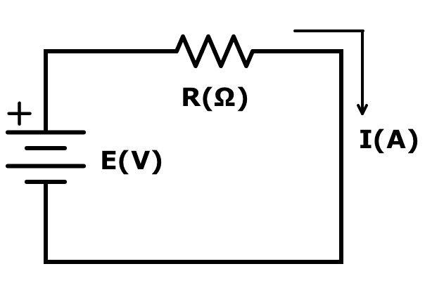 The three basic parameters of this circuit are electromotive force (E), current (I), and resistance (R). Electromotive force, or EMF, is the force that causes electrons to flow in a circuit. We use the letter E to denote electromotive force. Electromotive force is measured in volts, and we use the letter V to denote volts.
QUESTION: What is the electrical term for the electromotive force (EMF) that causes electron flow? (T5A05)
ANSWER: Voltage
QUESTION: What is the unit of electromotive force? (T5A11)
ANSWER: The volt
QUESTION: How much voltage does a mobile transceiver typically require? (T5A06)
ANSWER: About 12 volts
Current is the flow of electrons in a circuit. In the circuit above, the letter I stands for current. Current flows from the positive (+) terminal of the voltage source through the circuit to the negative terminal of the voltage source. Current is measured in amperes, and we use the letter A to stand for amperes.
QUESTION: What is the name for the flow of electrons in an electric circuit? (T5A03)
ANSWER: Current
QUESTION: Electrical current is measured in which of the following units? (T5A01)
ANSWER: Amperes
Because the polarity of the battery voltage never changes, the current will flow in only one direction through the circuit. We call this direct current, or DC.
QUESTION: What is the name for a current that flows only in one direction? (T5A04)
ANSWER: Direct current
Batteries supply direct current, or simply DC.
The type of current you get out of a wall socket is different from the current that you get from a battery. Unlike the battery, the polarity of the voltage changes from positive to negative on a regular basis. In fact, it changes polarity 120 times per second. This means that the current changes direction 120 times per second. Because of this, we call this alternating current, or AC.
QUESTION: What is the name for a current that reverses direction on a regular basis? (T5A09)
ANSWER: Alternating current
One of the most important parameters of an alternating current is its frequency. The frequency of an alternating current is equal to half the number of times it reverses direction.
QUESTION: What describes the number of times per second that an alternating current makes a complete cycle? (T5A12)
ANSWER: Frequency
QUESTION: What is the unit of frequency? (T5C05)
ANSWER: Hertz
1 Hz is equal to one cycle per second. An alternating current reverses polarity twice per cycle, so the frequency of the alternating current available from a wall socket is 60 Hz.
Resistance is the third parameter. As the name implies, resistance opposes the flow of electrons in a circuit. The higher the resistance, the smaller the current. We use the letter R to stand for resistance. Resistance is measured in ohms, and we use the Greek letter omega (Ω) to stand for ohms.
Conductors are materials that conduct electrical current well or, in other words, have a low resistance. We use copper wires to connect a power supply to a radio because copper wires are good conductors.
QUESTION: Which of the following is a good electrical conductor? (T5A07)
ANSWER: Copper
Silver is actually a better conductor than copper, but copper is a lot less expensive than silver. Often, you will see gold used as a conductor. Although it is not as good a conductor as either copper or silver, it doesn’t corrode like copper or silver. That makes it a good choice for switch or connector contacts.
Many times we need a material that does not conduct current very well. We call these materials insulators, and insulators have a high resistance. Plastics and glass are commonly used insulators.
QUESTION: Which of the following is a good electrical insulator? (T5A08)
ANSWER: Glass
Hams obey Ohm’s Law!
Ohm’s Law is the relationship between voltage, current, and the resistance in a DC circuit. When you know any two of these values, you can calculate the third.
The most basic equation for Ohm’s Law is E = I × R.
In other words, when you know the current flowing through a circuit and the resistance of the circuit, you can calculate the voltage across the circuit.
QUESTION: What formula is used to calculate voltage in a circuit? (T5D02)
ANSWER: Voltage (E) equals current (I) multiplied by resistance (R)
Using simple algebra, you can derive the other two forms of this equation. These two equations let you calculate the resistance in a circuit if you know the voltage and current or the current in a circuit if you know the voltage and resistance.
QUESTION: What formula is used to calculate resistance in a circuit? (T5D03)
ANSWER: Resistance (R) equals voltage (E) divided by current (I)
We can also write this formula as R = E / I.
QUESTION: What formula is used to calculate current in a circuit? (T5D01)
ANSWER: Current (I) equals voltage (E) divided by resistance (R)
This formula is written I = E / R.
Now, let’s look at some examples of how to apply Ohm’s Law.
QUESTION: What is the resistance of a circuit in which a current of 3 amperes flows through a resistor connected to 90 volts? (T5D04)
ANSWER: 30 ohms
Here’s how to calculate this answer: R = E / I = 90 V ÷ 3 A = 30 Ω
QUESTION: What is the resistance in a circuit for which the applied voltage is 12 volts and the current flow is 1.5 amperes? (T5D05)
ANSWER: 8 ohms
R = E / I = 12 V / 1.5 A = 8 Ω
QUESTION: What is the resistance of a circuit that draws 4 amperes from a 12-volt source? (T5D06)
ANSWER: 3 ohms
R = E / I = 12 V / 4 A = 3 Ω
QUESTION: What is the current in a circuit with an applied voltage of 120 volts and a resistance of 80 ohms? (T5D07)
ANSWER: 1.5 amperes
I = E / R = 120 V / 80 Ω = 1.5 A
QUESTION: What is the current through a 100-ohm resistor connected across 200 volts? (T5D08)
ANSWER: 2 amperes
I = E / R = 200 V / 100 Ω = 2 A
QUESTION: What is the current through a 24-ohm resistor connected across 240 volts? (T5D09)
ANSWER: 10 amperes
I = E / R = 240 V / 24 Ω = 10 A
QUESTION: What is the voltage across a 2-ohm resistor if a current of 0.5 amperes flows through it? (T5D10)
ANSWER: 1 volt
E = I × R = 0.5 A × 2 Ω = 1 V
QUESTION: What is the voltage across a 10-ohm resistor if a current of 1 ampere flows through it? (T5D11)
ANSWER: 10 volts
E = I × R = 1 A × 10 Ω = 10 V
QUESTION: What is the voltage across a 10-ohm resistor if a current of 2 amperes flows through it? (T5D12)
ANSWER: 20 volts
E = I × R = 2 A × 10 Ω = 20 V
Now, let’s consider circuits with two resistors instead of just a single resistor. There are two ways in which the two resistors can be connected: in series or in parallel. A series circuit looks like this:
There is only one path for the current to flow, so the same current flows through both resistors. And, because the voltage across the resistors is equal to I x R, the voltage across each of the resistors will depend on the value of the resistors. If R1 = R2, then the voltage will be the same across both resistors. If R1 does not equal R2, however, the voltages will be different. In either case, the sum of the two voltages will equal the voltage of the voltage source.
QUESTION: In which type of circuit is current the same through all components? (T5A13)
ANSWER: Series
QUESTION: What happens to current at the junction of two components in series? (T5D13)
ANSWER: It is unchanged
QUESTION: What is the voltage across each of two components in series with a voltage source? (T5D15)
ANSWER: It is determined by the type and value of the components
In a parallel circuit, both resistors are connected directly to the voltage source:
Because both components are connected directly to the voltage source, the voltage across them will be the same. This voltage will cause currents to flow in each of the resistors. I1 = V/R1, and I2 = V/R2. The total current, I, is equal to I1 + I2. If R1 = R2, then the same current flows through both resistors. If the resistors have different values, then I1 will be different from I2.
QUESTION: In which type of circuit is voltage the same across all components? (T5A14)
ANSWER: Parallel
QUESTION: What is the voltage across each of two components in parallel with a voltage source? (T5D16)
ANSWER: The same voltage as the source
QUESTION: What happens to current at the junction of two components in parallel? (T5D14)
ANSWER: It divides between them dependent on the value of the components
Power is the rate at which electrical energy is generated or consumed. Power is measured in watts, and the letter W is the symbol we use for watts.
QUESTION: Which term describes the rate at which electrical energy is used? (T5A10)
ANSWER: Power
QUESTION: What is the formula used to calculate electrical power in a DC circuit? (T5C08)
ANSWER: Power (P) equals voltage (E) multiplied by current (I)
We write this equation P = E × I.
QUESTION: Electrical power is measured in which of the following units? (T5A02)
ANSWER: Watts
Here are some examples:
QUESTION: How much power is being used in a circuit when the applied voltage is 13.8 volts DC and the current is 10 amperes? (T5C09)
ANSWER: 138 watts
The calculation for this question is P = E × I = 13.8 V × 10 A = 138 W.
QUESTION: How much power is being used in a circuit when the applied voltage is 12 volts DC and the current is 2.5 amperes? (T5C10)
ANSWER: 30 watts
The calculation for this question is P = E × I = 12 V × 2.5 A = 30 W.
Just as with Ohm’s Law, you can use algebra to come up with other forms of this equation to calculate the voltage if you know the power and the current, or to calculate the current if you know the power and the voltage. The formula to calculate the current, if you know the power and the voltage is I = P / E.
QUESTION: How many amperes are flowing in a circuit when the applied voltage is 12 volts DC and the load is 120 watts? (T5C11)
ANSWER: 10 amperes
The calculation for this question is I = P / E = 120 W ÷ 12 V = 10 A.
When dealing with electrical parameters, such as voltage, resistance, current, and power, we use a set of prefixes to denote various orders of magnitude:
| Prefix | Abbreviation | Numerical | Exponential |
| giga- | G | 1,000,000,000 | 109 |
| mega- | M | 1,000,000 | 106 |
| kilo- | k | 1,000 | 103 |
| —- | —- | 1 | 100 |
| milli- | m | 0.001 | 10-3 |
| micro- | μ,u | 0.000001 | 10-6 |
| nano- | n | 0.000000001 | 10-9 |
| pico- | p | 0.000000000001 | 10-12 |
Here are some examples:
QUESTION: How many milliamperes is 1.5 amperes? (T5B01)
ANSWER: 1500 milliamperes
QUESTION: What is another way to specify a radio signal frequency of 1,500,000 hertz? (T5B02)
ANSWER: 1500 kHz
QUESTION: How many volts are equal to one kilovolt? (T5B03)
ANSWER: One thousand volts
QUESTION: How many volts are equal to one microvolt? (T5B04)
ANSWER: One one-millionth of a volt
QUESTION: Which of the following is equal to 500 milliwatts? (T5B05)
ANSWER: 0.5 watts
QUESTION: How many microfarads are equal to 1,000,000 picofarads? (T5B08)
ANSWER: 1 microfarad
The farad is the unit of capacitance.
QUESTION: If an ammeter calibrated in amperes is used to measure a 3000-milliampere current, what reading would it show? (T5B06)
ANSWER: 3 amperes
QUESTION: What is the proper abbreviation for megahertz? (T5C14)
ANSWER: MHz
QUESTION: If a frequency display calibrated in megahertz shows a reading of 3.525 MHz, what would it show if it were calibrated in kilohertz? (T5B07)
ANSWER: 3525 kHz
QUESTION: Which of the following frequencies is equal to 28,400 kHz? (T5B12)
ANSWER: 28.400 MHz
QUESTION: If a frequency display shows a reading of 2425 MHz, what frequency is that in GHz? (T5B13)
ANSWER: 2.425 GHz
When dealing with ratios—especially power ratios—we often use decibels (dB). The reason for this is that the decibel scale is a logarithmic scale, meaning that we can talk about large ratios with relatively small numbers. When the value is positive, it means that there is a power increase. When the value is negative, it means that there is a power decrease.
At this point, you don’t need to know the formula used to calculate the ratio in dB, but you need to know the ratios represented by the values 3 dB, 6 dB, and 10 dB.
QUESTION: What is the approximate amount of change, measured in decibels (dB), of a power increase from 5 watts to 10 watts? (T5B09)
ANSWER: 3 dB
3 dB corresponds to a ratio of 2 to 1, and because going from 5 watts to 10 watts doubles the power, we can also say that there is a gain of 3 dB.
QUESTION: What is the approximate amount of change, measured in decibels (dB), of a power decrease from 12 watts to 3 watts? (T5B10)
ANSWER: −6 dB
6 dB corresponds to a ratio of 4 to 1, and a decrease in power from 12 watts to 3 watts is a ratio of 4 to 1. Because this is a power decrease, the value in dB is negative.
QUESTION: What is the amount of change, measured in decibels (dB), of a power increase from 20 watts to 200 watts? (T5B11)
ANSWER: 10 dB
Increasing the power from 20 watts to 200 watts is a ratio of 10 to 1, and 10 dB corresponds to a ratio of 10 to 1.
 This arrived in the mail the other day from the Boy Scouts Mason-Dixon Council. I thought it was very nice of them to send it to me, even though the PDF version of my Tech study guide is a free download. If you’re teaching a class, please feel free to have your students download a copy. Also, keep in mind that I offer instructor discounts on the print version. Please contact me if you’d like to order a quantity for your class.

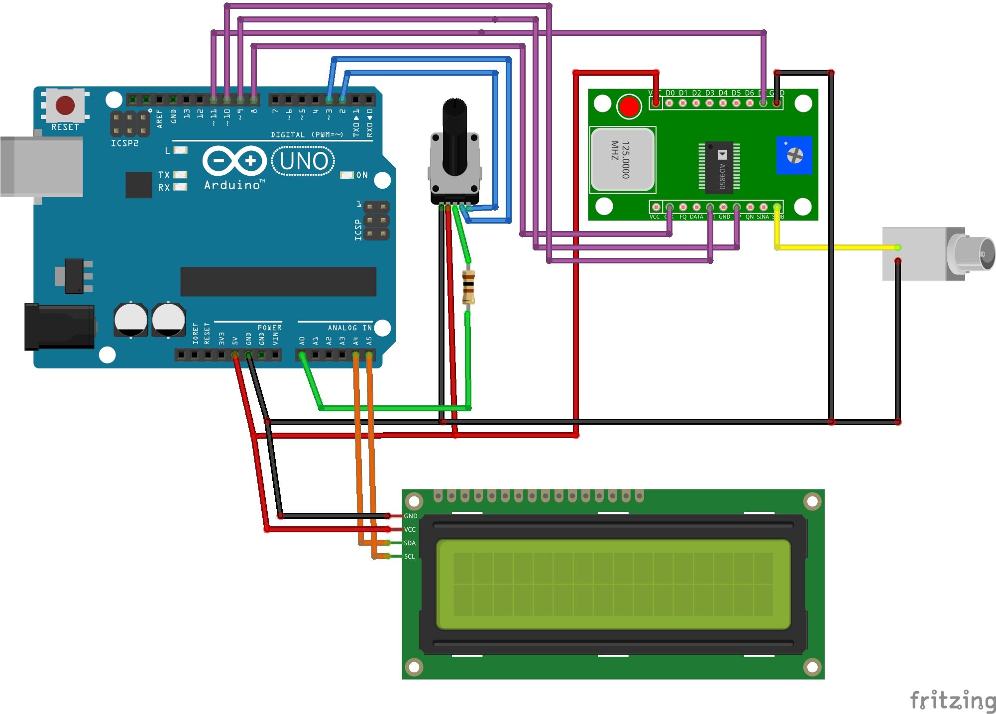
So, I’ve started on my next book project, Ham Radio for Hackers. It’s going to be a collection of projects based on the Arduino and Raspberry Pi, with a bunch of other “makerish” stuff thrown in.
One of the first projects, if not the first, is going to be an Arduino/AD9850 DDS VFO. I’m using AD7C’s version as the starting point for mine.
One of the issues one always has with writing a book is generating illustrations, such as schematics and assembly drawings. One of the great tools out there that helps immensely with this is Fritzing. I’ve written about Fritzing before, but never had the opportunity to really use it.
Now, I do. Below, see my first real Fritzing drawing. You can click on the image to get a larger, easier-to-read version of the diagram.
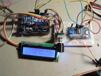
And here’s the breadboard:
 I got this email about an hour ago, and I’m still a little bit stunned by it. This reader wrote:
I purchased [your Extra Class study guide], and I am sorry, but it lacks what I need to follow and prepare for the exam. It is too disorganized. I could not recommend it to my worst enemy.
I’m stunned because I can honestly count on one hand the number of comments as negative as this, while it would take many, many hands to count the number of positive reviews. But, I guess you can’t please everyone.
I was going to email him back, first apologizing that the study guide didn’t do the trick for him and ask if he had any specific recommendations. I’m not so sure that’s worth the effort, though. What do you think?
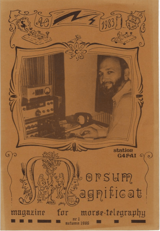 I forget exactly how this came to my attention., but being the CW geek that I am, I had to put this on my blog. Back issues of Morsum Magnificat, a delightfully homebrew magazine—what many of us called a ‘zine, back in the day—are now available online. Issue nr 1 of the English version, pictured at right, features articles on Jack Sykes, who, at the time was purported to be the last manufacturer of code keys in Britain; a transistorized sidetone oscillator to monitor a CW transmitter’s keying; and many other stories and news items about both landline and radio telegraphy. Please enjoy them.
Morsum Magnificat now available for free download
The English language edition of Morsum Magnificat, the Morse Magazine, otherwise known as “MM”, contained a vast amount of information and illustrations of interest to Morse operators, key collectors, historians, researchers and other Morse enthusiasts.
Published from 1986 to 2004, in 89 issues, with readers and contributors around the world, it covered every conceivable aspect of Morse telegraphy, past, present and future, in a truly international way.
With the permission of the copyright holder, Zyg Nilski, G3OKD, this vast resource is now available for download in PDF format, free of charge, thanks to the generosity of Lynn Burlingame N7CFO who was a reader of, and contributor to, MM.
Included in the downloads is an updated and revised version of the MM 54-page Key WT 8 Amp Worldwide Survey which has proved to be of great interest to both users and collectors of the many versions of this famous pre-war, wartime and post-war military Morse key.
MM was first published in the Dutch language, by Morse enthusiasts, Rinus Hellemons PA0BFN, and Dick Kraayveld PA3ALM. They were later joined by Tony Smith G4FAI who helped them launch the English language edition of the magazine.
After Rinus died, G4FAI produced and edited MM alone until he was joined by Geoff Arnold G3GSR, one-time editor of Practical Wireless and founder of Radio Bygones. Later, Zyg Nilski G3OKD took over as editor and produced the final 28 issues of the magazine.
Original readers of MM who have copies missing from their collection can now fill the gap with a digital download. Today’s newcomers, and those who missed it first time round, now have the opportunity to discover what this unique publication has to offer them, and it costs nothing!
Free downloads of MM are available for personal use only from: http://www.n7cfo.com/tgph/Dwnlds/mm/mm.htm
73 of the 89 issues have been posted so far. If anyone can provide any of the missing issues for scanning to complete the set please contact Lynn Burlingame at n7cfo(at)n7cfo.com
Copies of MM may not be downloaded or distributed for any commercial purpose. Any website offering digital downloads of Morsum Magnificat or the Key WT 8 Amp Worldwide Survey for payment is doing so without copyright permission. Anyone finding such a site is asked to send details to g4fai(at)btinternet.com
Tony Smith G4FAI
Co-founder of the English edition of Morsum Magnificat
I got a couple of nice e-mails from readers yesterday, and I thought I’d share them with you.
The first is from Ralph, KI7KNJ/AE. He writes:
FYI, I used your study guides and an online exam practice site and passed the Technician and General exams on the same night a month ago. Then I passed the Extra exam last night! I was pretty stoked to get through them all in such a short time.
I was very pleased with your study guides and recommend them to people wanting to get their licenses.
Rahul, KE0LUE writes:
Thank you very much for the nice guide/study books for Hams or new comers, I have studied your books & got my Tech & General License in one go.
Thanks for the kind words, guys. If you ever hear me on the air, I hope that you’ll give me a call.
Some of the advice may seem contradictory. For example, lesson #1 is to avoid being obsessed with amateur radio, yet one of the chapters is titled, “Commitment is king.” Life is like that, though, isn’t it? The trick is being able to resolve those conflicting ideas in our lives. In this case that means not being obsessed with the hobby while at the same time being committed to it. Without commitment you won’t get as much out of amateur radio as you might expect, but you still do need to be able to step away when you need to as well.
One of the chapters that really resonated with me is “Finishing Projects (or Not).” I have numerous half-completed projects on my workbench, and when I think about them, I feel bad that I haven’t finished them. DH7LM offers several bits of advice here, including choosing projects wisely, and to trick yourself into finishing them by postponing other ham radio purchases until you do complete a particular project.
New hams (and old hams) will find lots of practical advice in this book. It won’t help you operate the latest digital mode, or help you work more DX, but it will help you get more out of amateur radio.