• Skip to primary navigation
  • Skip to main content
  • Skip to primary sidebar
  • Skip to footer

KB6NU's Ham Radio Blog

KB6NU's Ham Radio Blog
  • HOME
  • Study Guides
  • Teach a One-Day Tech Class
  • W8SRC Repeater Guide
  • Advertise
  • Hire Me

Books and Magazines

2019 No Nonsense General Class Study Guide: Operating Procedures, part I

March 2, 2019 By Dan KB6NU 3 Comments

Phone operating procedures, USB/LSB utilization conventions, procedural signals, breaking into a QSO in progress, VOX operation

On the HF bands, the most common mode used for voice communications is single sideband, or SSB. SSB is a type of amplitude modulation, or AM. In the process of amplitude modulation, a transmitter generates an upper sideband and a lower sideband, in addition to the carrier signal. Back in the early days of radio, a smart guy figured out all of the information in a voice signal is carried in one of the sidebands, and that it would be more efficient to filter out the carrier and one of the sidebands and put all of the power of a radio signal into a single sideband. In addition to voice communications, SSB is also used to transmit digital information on the HF bands.

QUESTION: Which mode of voice communication is most commonly used on the HF amateur bands? (G2A05)
ANSWER: Single sideband

QUESTION: Which of the following statements is true of the single sideband voice mode? (G2A07)
ANSWER: Only one sideband is transmitted; the other sideband and carrier are suppressed

QUESTION: Which of the following is an advantage when using single sideband, as compared to other analog voice modes on the HF amateur bands? (G2A06)
ANSWER: Less bandwidth used and greater power efficiency

A single sideband signal can be either upper sideband signal can be either upper sideband (USB) or lower sideband (LSB), but USB is the most commonly used sideband. USB is used almost exclusively on frequencies above 14 MHz, including the VHF and UHF bands, as well as on the 60 m band, while LSB is used on the 160 m, 75 m, and 40 m bands. There’s no particular technical reason for this. It’s just current amateur practice to do so.

QUESTION: Which sideband is most commonly used for voice communications on frequencies of 14 MHz or higher? (G2A01)
ANSWER: Upper sideband

QUESTION: Which mode is most commonly used for voice communications on the 17-meter and 12-meter bands? (G2A04)
ANSWER: Upper sideband

QUESTION: Which of the following is most commonly used for SSB voice communications in the VHF and UHF bands? (G2A03)
ANSWER: Upper sideband
QUESTION: Which of the following modes is most commonly used for voice communications on the 160-meter, 75-meter, and 40-meter bands? (G2A02)
ANSWER: Lower sideband

QUESTION: Why do most amateur stations use lower sideband on the 160-meter, 75-meter, and 40-meter bands? (G2A09)
ANSWER: It is good amateur practice


To establish a contact on the HF bands, you can call CQ or reply to a CQ. Sometimes you’ll hear stations calling “CQ DX” instead of simply CQ. If the station calling CQ DX is located in the contiguous 48 states, then the operator is looking to make contacts outside of the U.S., and if you’re not outside of those states, it is good operating procedure not to answer that call.

QUESTION: Generally, who should respond to a station in the contiguous 48 states who calls “CQ DX”? (G2A11)
ANSWER: Any stations outside the lower 48 states

Another way to establish a contact is to break into a conversation that’s already in progress. To do this, simply say your callsign when there is a lull in the conversation.

QUESTION: What is the recommended way to break in to a phone contact? (G2A08)
ANSWER: Say your call sign once


Before making contacts, make sure that you set the microphone gain to the appropriate level. Setting the microphone gain too low will reduce the output power of your transmitter. Setting it too high will result in distorted audio and spurious emissions. Refer to your transceiver’s user manual for instructions on how to do this.

QUESTION: What control is typically adjusted for proper ALC setting on an amateur single sideband transceiver? (G2A12)
ANSWER: Transmit audio or microphone gain


When operating SSB, many amateurs like to use the VOX, or voice-operated control, instead of push-to-talk, or PTT, operation. Using VOX frees up an operator’s hands to do things like adjust controls or log contacts.

QUESTION: Which of the following statements is true of voice VOX operation versus PTT operation? (G2A10)
ANSWER: It allows “hands free” operation


Operating courtesy; band plans; emergencies, including drills and emergency communications

Whenever you’re operating, courtesy should always be a consideration when selecting a frequency. The courteous thing to do is to select an operating frequency so that you do not interfere with other stations operating on nearby frequencies. You can avoid interference with other stations by ensuring that the frequency you want to use is not already in use. Remember that on many HF bands you may only be able to hear one station and not the other, so before calling, ask if the frequency is in use.

When operating phone, you simply ask if the frequency is in use. When operating CW, you send the Q signal QRL?

QUESTION: What is a practical way to avoid harmful interference on an apparently clear frequency before calling CQ on CW or phone? (G2B06)
ANSWER: Send “QRL?” on CW, followed by your call sign; or, if using phone, ask if the frequency is in use, followed by your call sign

QUESTION: What does the Q signal “QRL?” mean? (G2C04)
ANSWER: “Are you busy?”, or “Is this frequency in use?”

Another way to avoid interference is to follow the voluntary band plan for the mode you’re using. For example, most band plans call for SSTV operation around 14.230 MHz. So, if you’re operating SSB, you probably want to avoid that frequency.

QUESTION: Which of the following complies with good amateur practice when choosing a frequency on which to initiate a call? (G2B07)
ANSWER: Follow the voluntary band plan for the operating mode you intend to use

Some band plans may denote a frequency or small band of frequencies as the DX window for that band. What that means is that U.S.. stations are not to call inside that window to allow DX stations to be heard. In the 6 m band, the DX window is 50.1 – 50.25 MHz.

QUESTION: What is the voluntary band plan restriction for U.S. station transmitting within the 48 contiguous states in the 50.1 to 50.125 MHz band segment? (G2B08)
ANSWER: Only contacts with stations not within the 48 contiguous states


Another thing you should do to avoid interference is to make sure that the frequency you wish to use is not too close to other stations.

QUESTION: When selecting an SSB transmitting frequency, what minimum separation should be used to minimize interference to stations on adjacent frequencies? (G2B05)
ANSWER: Approximately 3 kHz

QUESTION: When selecting a CW transmitting frequency, what minimum separation should be used to minimize interference to stations on adjacent frequencies? (G2B04)
ANSWER: 150 to 500 Hz


Band conditions can change during the course of a contact. When this happens, you may find that your contact is now being interfered with by stations that you could not hear previously or that you are interfering with stations that could not hear you previously. Should this occur, the courteous thing to do is to simply move your contact to another open frequency.

QUESTION: What is good amateur practice if propagation changes during a contact and you notice interference from other stations on the frequency? (G2B03)
ANSWER: Attempt to resolve the interference problem with the other stations in a mutually acceptable manner


One thing to keep in mind is that no one “owns” a frequency, no matter how long it has been their practice to use the frequency. Even nets don’t have the right to kick you off a frequency.

QUESTION: Which of the following is true concerning access to frequencies in non-emergency situations? (G2B01)
ANSWER: Except during FCC declared emergencies, no one has priority access to frequencies, common courtesy should be a guide


It’s also important to know what to do if you hear a station in an emergency situation. While the rules are very strict regarding normal operation of an amateur radio station, an amateur station is allowed to do just about anything to assist another station in distress during an actual emergency. This means using frequencies outside of the amateur bands and using high power should the situation require it.

QUESTION: When is an amateur station allowed to use any means at its disposal to assist another station in distress? (G2B10)
ANSWER: At any time during an actual emergency

QUESTION: What frequency should be used to send a distress call? (G2B11)
ANSWER: Whichever frequency has the best chance of communicating the distress message

Helping that station in distress should become your first priority. The first thing you should do if you are communicating with another amateur station and hear a station in distress break in is to figure out how to help them.

QUESTION: What is the first thing you should do if you are communicating with another amateur station and hear a station in distress break in? (G2B02)
ANSWER: Acknowledge the station in distress and determine what assistance may be needed


In certain emergencies, government officials might activate the Radio Amateur Civil Emergency Service (RACES), a protocol created by the Federal Emergency Management Agency (FEMA) and the Federal Communications Commission. To be a part of RACES, you must be a licensed radio amateur and be certified by a civil defense agency.

QUESTION: Who may be the control operator of an amateur station transmitting in RACES to assist relief operations during a disaster? (G2B09)
ANSWER: Only a person holding an FCC issued amateur operator license


CW operating procedures and procedural signals, Q signals and common abbreviations, full break in

When establishing a CW contact with another station, the sending and receiving stations should always synchronize their speed. You might be a real speed demon, but if you want to answer a CQ being sent at a speed much slower than the speed at which you can send and receive, then you should slow down to accommodate the slower operator. Likewise, if you’re not comfortable sending and receiving at the speed of a station calling CQ, reply at a lower speed. A good operator will then slow down to accommodate you.

QUESTION: What is the best speed to use when answering a CQ in Morse code? (G2C05)
ANSWER: The fastest speed at which you are comfortable copying, but no faster than the CQ

When answering a CQ, you should set the frequency of your transceiver so that it matches the frequency of the sending station. We call this process “zero beating.” One reason for doing this is that it makes it easier for the calling station to find you. Another reason is that your contact will require less bandwidth.

QUESTION: What does the term “zero beat” mean in CW operation? (G2C06)
ANSWER: Matching the transmit frequency to the frequency of a received signal


After establishing contact, it’s customary to send the other station a signal report. This report consists of three numbers that correspond to the readability, strength, and tone of the signal. Hams sometimes call this the RST report. When appropriate, an operator may append a letter to the RST report. For example, to denote that a signal has a chirp, you would append the letter “C.”

QUESTION: When sending CW, what does a “C” mean when added to the RST report? (G2C07)
ANSWER: Chirpy or unstable signal


During the course of a CW contact, it’s good practice to use Q signals to shorten the number of characters that you must send and which the receiving station needs to receive. Q signals are three letter combinations that begin with the letter “Q.” There are many different Q signals, but you only need to know four of them to pass the test.

QUESTION: What should you do if a CW station sends “QRS?” (G2C02)
ANSWER: Send slower

QUESTION: What does the Q signal “QSL” mean? (G2C09)
ANSWER: I acknowledge receipt

QUESTION: What does the Q signal “QRN” mean? (G2C10)
ANSWER: I am troubled by static

QUESTION: What does the Q signal “QRV” mean? (G2C11)
ANSWER: I am ready to receive messages


CW operators also use what are called prosigns. Prosigns can indicate what an operator intends to do or calls for the other operator to do something. For example, the prosign “K” is an invitation to other stations to begin transmitting. “KN” is also an invitation to transmit, but only a specific station, usually the station with which a station is already in contact.

QUESTION: What does it mean when a CW operator sends “KN” at the end of a transmission? (G2C03)
ANSWER: Listening only for a specific station or stations

QUESTION: What prosign is sent to indicate the end of a formal message when using CW? (G2C08)
ANSWER: AR


When operating CW, some hams simply mute their receivers during a transmission. The problem with this approach is that the other operator cannot break in to make a comment. Another problem is that you can’t hear if another station is interfering with your transmission. To get around these problems, hams use “break-in mode,” or QSK.

QUESTION: Which of the following describes full break-in telegraphy (QSK)? (G2C01)
ANSWER: Transmitting stations can receive between code characters and elements
Filed Under: Books and Magazines, Classes/Testing/Licensing Tagged With: study guides

2019 No Nonsense General Class Study Guide: Amateur Radio Practices, part II

February 26, 2019 By Dan KB6NU 1 Comment

Interference with consumer electronics, grounding, DSP

At some point or another, your amateur radio station will interfere with a radio or television set, a PA system, or a telephone. A SSB transmission generally causes some kind of humming, while a CW transmission can cause humming or clicking. Sometimes this may be your fault, other times it may be the fault of the device. In either case, you should do everything you can to eliminate this interference.

QUESTION: What sound is heard from an audio device or telephone if there is interference from a nearby single sideband phone transmitter? (G4C03)
ANSWER: Distorted speech

QUESTION: What is the effect on an audio device when there is interference from a nearby CW transmitter? (G4C04)
ANSWER: On-and-off humming or clicking

Fortunately, there are many things you can do to reduce or eliminate the interference. For example, you might connect a bypass capacitor across speaker leads to reduce interference to an audio device. To reduce RF picked up by audio cables, you might use a snap-on ferrite choke. I often advise amateurs to have a handful of these on hand for this type of application.

QUESTION: Which of the following might be useful in reducing RF interference to audio frequency devices? (G4C01)
ANSWER: Bypass capacitor

QUESTION: Which of the following would reduce RF interference caused by common-mode current on an audio cable? (G4C08)
ANSWER: Placing a ferrite choke around the cable


Proper grounding is also important to reduce interference. Rather than connecting the grounds in a daisy-chain fashion, you should connect them all to a single point. This will help you avoid ground loops, which can cause a hum on your phone signal.

QUESTION: How can a ground loop be avoided? (G4C09)
ANSWER: Connect all ground conductors to a single point

QUESTION: What could be a symptom of a ground loop somewhere in your station? (G4C10)
ANSWER: You receive reports of “hum” on your station’s transmitted signal

When grounding RF equipment, keep ground cables short and direct to prevent high-impedance or resonant ground connections. A long ground wire may present a high impedance at HF frequencies and instead of grounding station equipment enclosures may cause high voltages to be present. This, in turn, may cause operators to receive an RF burn when touching the enclosure. Also be sure to “bond” the enclosures together to prevent any potential differences that can cause hazard voltages, or “hot spots,” between the enclosures.

QUESTION: What effect can be caused by a resonant ground connection? (G4C06)
ANSWER: High RF voltages on the enclosures of station equipment.

QUESTION: What might be the problem if you receive an RF burn when touching your equipment while transmitting on an HF band, assuming the equipment is connected to a ground rod? (G4C05)
ANSWER: The ground wire has high impedance on that frequency

QUESTION: Why must the metal enclosure of every item of station equipment be grounded? (G4C13)
ANSWER: It ensures that hazardous voltages cannot appear on the chassis

QUESTION: What technique helps to minimize RF “hot spots” in an amateur station? (G4C11)
ANSWER: Bonding all equipment enclosures together


A common complaint of amateur radio operators is electrical noise that seems to be on every band. This may be caused by arcing in a power line transformer or at some other connection.

QUESTION: Which of the following could be a cause of interference covering a wide range of frequencies? (G4C02)
ANSWER: Arcing at a poor electrical connection

One way to eliminate noise is to use digital signal processor, or DSP. Modern amateur radio transceivers have built-in DSPs that operate at IF frequencies. DSP filters generally work better than analog filters.

QUESTION: Which of the following is an advantage of a receiver DSP IF filter as compared to an analog filter? (G4C12)
ANSWER: A wide range of filter bandwidths and shapes can be created


Speech processors, S meters, sideband operation near band edges

Speech processors can be very useful when operating SSB. Speech processors increase the average power output of an SSB transmitter, thereby increasing the intelligibility of the signal when conditions are poor.

QUESTION: What is the purpose of a speech processor as used in a modern transceiver? (G4D01)
ANSWER: Increase the intelligibility of transmitted phone signals during poor conditions

QUESTION: Which of the following describes how a speech processor affects a transmitted single sideband phone signal? (G4D02)
ANSWER: It increases average power

Of course, you must adjust it properly to gain these benefits. An incorrectly adjusted speech processor can cause more problems than it solves.

QUESTION: Which of the following can be the result of an incorrectly adjusted speech processor?(G4D03)
ANSWER: All of these choices are correct
• Distorted speech
• Splatter
• Excessive background pickup


Most commercial receivers have an S meter that indicates received signal strength. The S meter uses a logarithmic scale, with an increase of one S unit being equivalent to a gain of 6 dB. What that means is that a signal whose S meter reading is one unit higher than another is four times as strong as the other signal.

QUESTION: Where is an S meter found? (G4D06)
ANSWER: In a receiver

QUESTION: What does an S meter measure? (G4D04)
ANSWER: Received signal strength

QUESTION: How much must the power output of a transmitter be raised to change the S meter reading on a distant receiver from S8 to S9? (G4D07)
ANSWER: Approximately 4 times

QUESTION: How does a signal that reads 20 dB over S9 compare to one that reads S9 on a receiver, assuming a properly calibrated S meter? (G4D05)
ANSWER: It is 100 times stronger


When operating near band edges, it’s important to know the frequency range that your signal will actually occupy so that your transmissions stay within the amateur band. When operating lower sideband, or LSB, your signal actually occupies a 3 kHz space below the displayed carrier frequency, so you don’t want to set your transceiver to a frequency less than 3 kHz above the band edge when operating LSB. So, for example, the lowest frequency on which a General Class operator can operate phone is 7.175 MHz, so you should not set your radio to a frequency less than 7.178 MHz to make sure that your transmitted signal stays within the General Class portion of the band.

QUESTION: How close to the lower edge of the phone segment should your displayed carrier frequency be when using 3 kHz wide LSB? (G4D10)
ANSWER: At least 3 kHz above the edge of the segment

QUESTION: What frequency range is occupied by a 3 kHz LSB signal when the displayed carrier frequency is set to 7.178 MHz? (G4D08)
ANSWER: 7.175 to 7.178 MHz

Similarly, when operating USB, your signal occupies a space starting at the displayed carrier frequency and extending up 3 kHz. So, to stay within your assigned band, you should not set your transceiver to a frequency that is higher than 3 kHz below the upper band edge.

QUESTION: How close to the upper edge of the phone segment should your displayed carrier frequency be when using 3 kHz wide USB? (G4D11)
ANSWER: At least 3 kHz below the edge of the band

QUESTION: What frequency range is occupied by a 3 kHz USB signal with the displayed carrier frequency set to 14.347 MHz? (G4D09)
ANSWER: 14.347 to 14.350 MHz


HF mobile radio installations; emergency and battery powered operation

Operating mobile, that is from a car or boat, is an activity enjoyed by many radio amateurs. Amateurs can do almost everything from a mobile station that they can do at a fixed station.
When setting up a mobile station, the first thing to consider is how you are going to supply power to your radios. In general, it’s preferable to wire your transceiver directly to the vehicle’s battery with connections as short as possible, using heavy gauge wire.

QUESTION: Which of the following direct, fused power connections would be the best for a 100 watt HF mobile installation? (G4E03)
ANSWER: To the battery using heavy gauge wire

QUESTION: Why is it best NOT to draw the DC power for a 100 watt HF transceiver from a vehicle’s auxiliary power socket? (G4E04)
ANSWER: The socket’s wiring may be inadequate for the current being drawn by the transceiver


One common complaint when operating mobile is that the vehicle’s electronics generate noise that interferes with sensitive HF receivers. There are many sources of RF noise in a vehicle.

QUESTION: Which of the following may cause receive interference in a radio installed in a vehicle? (G4E07)
ANSWER: All of these choices are correct
• The battery charging system
• The fuel delivery system
• The vehicle control computer


As you can imagine, mobile antennas for HF operation are always a compromise because they are so short with respect to wavelength. The reason for this is that mobile HF antennas are much shorter than full-size antennas.

QUESTION: Which of the following most limits an HF mobile installation? (G4E05)
ANSWER: The antenna system

QUESTION: What is one disadvantage of using a shortened mobile antenna as opposed to a full-size antenna? (G4E06)
ANSWER: Operating bandwidth may be very limited

One way to make a physically short antenna resonate on HF is to use a capacitance hat. Like a loading coil, a capacitance hat makes an antenna seem electrically longer than it really is. Because mobile antennas are so short, the voltage at the tip of the antenna may be very high. To reduce the possibility of a high-voltage discharge, some mobile antennas have a corona ball. This ball disperses the charge at the tip of an antenna, thereby decreasing the voltage.

QUESTION: What is the purpose of a capacitance hat on a mobile antenna? (G4E01)
ANSWER: To electrically lengthen a physically short antenna

QUESTION: What is the purpose of a corona ball on an HF mobile antenna? (G4E02)
ANSWER: To reduce RF voltage discharge from the tip of the antenna while transmitting


Some amateurs use solar cells to power their equipment while operating mobile or portable. Solar cells take advantage of a process called photovoltaic conversion to convert the power of the sun into electrical power.

QUESTION: What is the name of the process by which sunlight is changed directly into electricity? (G4E08)
ANSWER: Photovoltaic conversion
QUESTION: What is the approximate open-circuit voltage from a fully illuminated silicon photovoltaic cell? (G4E09)
ANSWER: 0.5 VDC

Some amateurs use photovoltaic cells to recharge storage batteries. These systems often have a series diode connected between a solar panel and the battery to prevent the battery from discharging through the solar panel when the sun isn’t shining.

QUESTION: What is the reason that a series diode is connected between a solar panel and a storage battery that is being charged by the panel? (G4E10)
ANSWER: The diode prevents self discharge of the battery though the panel during times of low or no illumination

Some amateurs even use wind power as a power source. Like other power sources, wind has advantages and disadvantages.

QUESTION: Which of the following is a disadvantage of using wind as the primary source of power for an emergency station? (G4E10)
ANSWER: A large energy storage system is needed to supply power when the wind is not blowing

Filed Under: Books and Magazines, Classes/Testing/Licensing Tagged With: study guides

2019 No Nonsense General Class Study Guide: Amateur Radio Practices, part I

February 25, 2019 By Dan KB6NU 2 Comments

Station operation and set up

Modern HF transceivers have features that make operating a breeze, but to use them properly, you have to know when to use them and how to use them. The notch filter is a good example. The notch filter actually introduces a notch into a receiver’s passband to block interfering signals.

QUESTION: What is the purpose of the “notch filter” found on many HF transceivers? (G4A01)
ANSWER: To reduce interference from carriers in the receiver passband

Another feature that helps reduce interference from nearby stations is the IF shift control. It shifts the passband of the IF filter to the right or left of the center frequency.

QUESTION: Which of the following is a use for the IF shift control on a receiver? (G4A11)
ANSWER: To avoid interference from stations very close to the receive frequency

One type of interference is called overload. This occurs when a strong incoming signal is close to the frequency that you’re monitoring. To help prevent this type of interference, many transceivers have an attenuator, which you can switch in to reduce the signal level reaching the RF amplifiers.

QUESTION: What is one reason to use the attenuator function that is present on many HF transceivers? (G4A13)
ANSWER: To reduce signal overload due to strong incoming signals

Noise is quickly becoming a big problem for amateur radio operators, whether it be from power lines, atmospheric noise, or man-made noise from electronic devices in one’s home or neighbors’ homes. To combat this, most modern transceivers have noise blankers and noise reducers. Noise blankers attempt to reduce pulse type noise, such as from a car ignition, by reducing the receiver gain during a noise pulse. Noise reducers are designed to reduce the level from other types of noise. One disadvantage of a noise reducer is that when you increase the noise reduction level, the incoming signal may become distorted.

QUESTION: How does a noise blanker work? (G4A16)
ANSWER: By reducing receiver gain during a noise pulse

QUESTION: What happens as the noise reduction control level in a receiver is increased? (G4A17)
ANSWER: Received signals may become distorted

Modern transceivers also have features that make operating CW more convenient and effective. For example, most transceivers nowadays have built-in electronic keyers. Keyers automatically generate dots and dashes (dits and dahs) of exactly the same length and evenly space them as well.


Another feature designed for easier CW operation is the ability to select which sideband that you want to use to receive a CW signal. This feature can reduce or eliminate interference from signals in the receiver passband. By selecting the opposite, or “reverse,” sideband, you shift the receiver’s passband up or down, so that the interfering signal can no longer be heard.

QUESTION: What is the purpose of an electronic keyer? (G4A10)
ANSWER: Automatic generation of strings of dots and dashes for CW operation

QUESTION: What is one advantage of selecting the opposite, or “reverse,” sideband when receiving CW signals on a typical HF transceiver? (G4A02)
ANSWER: It may be possible to reduce or eliminate interference from other signals

Many modern transceivers also have the ability to receive on one frequency and send on another. This is called “split mode.” Some high-end transceivers also have two or more variable frequency oscillators, or VFOs. Both of these features allow you to receive on one frequency and transmit on another.

These features are especially useful when operating DX, that is when contacting foreign stations. You set your receiver frequency to the frequency on which the DX station is calling and your transmitter frequency to a frequency that won’t interfere with the DX station. That allows everyone to hear the DX station and allows the DX station operator to hear and call stations trying to call him or her. If your radio has only a single VFO, it switches rapidly between the transmit and receive frequencies. If your radio has two VFOs, it can monitor both frequencies simultaneously.

QUESTION: What is normally meant by operating a transceiver in “split” mode? (G4A03)
ANSWER: The transceiver is set to different transmit and receive frequencies

QUESTION: Which of the following is a common use for the dual-VFO feature on a transceiver? (G4A12)
ANSWER: To permit monitoring two different frequencies

It has become quite popular to operate “digital modes” by supplying an audio signal, usually from a computer sound card, to a transceiver set to transmit single sideband. This type of operation is called audio frequency shift keying, or AFSK, because the audio tones will shift the transmitted frequency.

In order to send a clean signal, you must set the mic gain and automatic level control (ALC) properly. If not set properly, your signal could become distorted and you might actually transmit spurious signals.

QUESTION: What is likely to happen if a transceiver”s ALC system is not set properly when transmitting AFSK signals with the radio using single sideband mode? (G4A14)
ANSWER: Improper action of ALC distorts the signal and can cause spurious emissions

One problem that may occur when transmitting AFSK signals is that the audio cable or USB cable connecting the computer to the radio may pick up stray RF. Should this happen, your signal might become distorted or the radio might be disconnected from the computer.

QUESTION: Which of the following can be a symptom of transmitted RF being picked up by an audio cable carrying AFSK data signals between a computer and a transceiver? (G4A15)
ANSWER: All of these choices are correct
– The VOX circuit does not un-key the transmitter
– The transmitter signal is distorted
– Frequent connection timeouts

Many amateurs buy linear amplifiers to make their signals stronger. Knowing how to set the controls on a linear amplifier, including the load or coupling control, ALC, and drive power, is important so that you transmit clean signals and avoid damaging the amplifier.

QUESTION: What is the correct adjustment for the load or coupling control of a vacuum tube RF power amplifier? (G4A08)
ANSWER: Maximum power output without exceeding maximum allowable plate current

QUESTION: What reading on the plate current meter of a vacuum tube RF power amplifier indicates correct adjustment of the plate tuning control? (G4A04)
ANSWER: A pronounced dip

QUESTION: What is a reason to use Automatic Level Control (ALC) with an RF power amplifier? (G4A05)
ANSWER: To reduce distortion due to excessive drive

QUESTION: What condition can lead to permanent damage to a solid-state RF power amplifier? (G4A07)
ANSWER: Excessive drive power

When using a linear amplifier, a time delay is sometimes included in a transmitter keying circuit. The reason for this is to give the system time to completelyl change over from receive to transmit operation.

QUESTION: Why is a time delay sometimes included in a transmitter keying circuit? (G4A09)
ANSWER: To allow time for transmit-receive changeover operations to complete properly before RF output is allowed

Antenna tuners, also known as antenna couplers, are also common accessories in an amateur radio station. They ensure a good match between the transmitter and the antenna system.

QUESTION: What type of device is often used to match transmitter output impedance to an impedance not equal to 50 ohms? (G4A06)
ANSWER: Antenna coupler or antenna tuner

Test and monitoring equipment, two-tone test

When you set up your amateur radio station, sometimes called your “shack,” you’ll not only want to acquire radios, but also some test equipment. The most basic piece of test equipment is the voltmeter. Voltmeters may be either analog or digital, but most amateurs now choose digital meters because they are cheaper and more accurate than analog meters. One of the reasons that digital voltmeters are more accurate is that they have a higher input impedance than analog voltmeters. The higher input impedance reduces the load on the circuit being tested, and thereby improves the accuracy.

QUESTION: What is an advantage of a digital voltmeter as compared to an analog voltmeter? (G4B06)
ANSWER: Better precision for most uses
QUESTION: Why is high input impedance desirable for a voltmeter? (G4B05)
ANSWER: It decreases the loading on circuits being measured

The use of an analog meter might, however, be preferred over a digital meter in some applications. The reason for this is that with an analog meter you can more easily see how a circuit’s output changes as you tune it.

QUESTION: What is an instance in which the use of an instrument with analog readout may be preferred over an instrument with a digital readout? (G4B14)
ANSWER: When adjusting tuned circuits

An oscilloscope is another handy piece of test equipment to have in your shack. With an oscilloscope, you can see how the amplitude of complex waveforms change over time. To do this, they have both vertical and horizontal amlifiers, that let you adjust the scale of the amplitude and the time period that you see on the screen.

QUESTION: What item of test equipment contains horizontal and vertical channel amplifiers? (G4B01)
ANSWER: An oscilloscope

QUESTION: Which of the following is an advantage of an oscilloscope versus a digital voltmeter? (G4B02)
ANSWER: Complex waveforms can be measured

One application for an oscilloscope is to check the keying waveform of a CW transmitter. With an oscilloscope, you can see how fast the RF signal reaches full amplitude when the transmitter is keyed, and how quickly the signals falls off when the key is released. Because oscilloscopes are not designed to handle high power, you must attenuate the transmitter output before connecting the oscilloscope.

QUESTION: Which of the following is the best instrument to use when checking the keying waveform of a CW transmitter? (G4B03)
ANSWER: An oscilloscope

QUESTION: What signal source is connected to the vertical input of an oscilloscope when checking the RF envelope pattern of a transmitted signal? (G4B04)
ANSWER: The attenuated RF output of the transmitter

Antenna analyzers are instruments that can measure a number of different parameters associated with antennas, such as SWR and coaxial cable impedance. To make measurements with an antenna analyzer, you disconnect the antenna system from the transmitter and connect it to the analyzer. One problem that you may encounter is that nearby transmitters can affect measurements that you make with an antenna analyzer. The reason for this is that the antenna being analyzed will pick up RF energy from the nearby transmitters, and this energy will be read as excessive reflected power.

QUESTION: Which of the following must be connected to an antenna analyzer when it is being used for SWR measurements? (G4B11)
ANSWER: Antenna and feed line

QUESTION: What is a use for an antenna analyzer other than measuring the SWR of an antenna system? (G4B13)
ANSWER: Determining the impedance of coaxial cable

QUESTION: What problem can occur when making measurements on an antenna system with an antenna analyzer? (G4B12)
ANSWER: Strong signals from nearby transmitters can affect the accuracy of measurements

Another instrument that you can use to make SWR measurements is a directional wattmeter. To measure the SWR with a direction wattmeter, you first measure the forward power, then the reverse power, and finally calculate the SWR with the equation: SWR = (1 + √(Pr/Pf))/(1- √(Pr/Pf)).

QUESTION: Which of the following can be determined with a directional wattmeter? (G4B10)
ANSWER: Standing wave ratio

The field strength meter is another instrument useful for making antenna measurements. You can use a field strength meter to make relative field strength readings, and by making a series of these readings in a circle around an antenna determine the antenna’s radiation pattern.

QUESTION: Which of the following instruments may be used to monitor relative RF output when making antenna and transmitter adjustments? (G4B08)
ANSWER: A field-strength meter

QUESTION: Which of the following can be determined with a field strength meter? (G4B09)
ANSWER: The radiation pattern of an antenna

To test the linearity of an SSB transmitter, you run a test called the two-tone test. You modulate the transmitter with two non-harmonically related tones, usually 700 Hz and 1900 Hz. If the transmitter is perfectly linear, those two tones will appear on the output. If not, non-linear products of those two frequencies will appear on the transmitter output, and you’ll be able to detect those products using an oscilloscope or spectrum analyzer.

QUESTION: What type of transmitter performance does a two-tone test analyze? (G4B15)
ANSWER: Linearity

QUESTION: What signals are used to conduct a two-tone test? (G4B07)
ANSWER: Two non-harmonically related audio signals

Filed Under: Books and Magazines, Classes/Testing/Licensing, Gear/Gadgets, Test Equipment Tagged With: study guides

2019 No Nonsense General Class Study Guide: Radio Wave Propagation

February 22, 2019 By Dan KB6NU 1 Comment

Sunspots and solar radiation, ionospheric disturbances, propagation forecasting, and indices

Amateur radio communications are subject to the whims of nature. Many different phenomena affect the propagation of signals, and it behooves you to know a little something about the phenomena. Doing so will make you a more effective amateur radio communicator.

The phenomenon that most affects amateur radio communications on the HF bands is the sunspot cycle. During a cycle, which lasts approximately 11 years, the number of sunspots varies from none to a high of between 100 and 200. In general, the more sunspots, the better is HF propagation.

QUESTION: What is the significance of the sunspot number about HF propagation? (G3A01)
ANSWER: Higher sunspot numbers generally indicate a greater probability of good propagation at higher frequencies

Because counting sunspots is a relatively subjective measure of solar activity, scientists have come up with a more objective measurement, called solar flux. As the sunspot number, or SSN, varies from 0 to around 200, the solar flux varies from around 60 to 300.

QUESTION: What is the solar flux index? (G3A05)
ANSWER: A measure of solar radiation at 10.7 centimeters wavelength

Some bands, such as 20 meters, can usually be counted on to provide good propagation at any point in the solar cycle, at least during daylight hours. The higher frequency bands are less reliable, though.

QUESTION: At what point in the solar cycle does the 20-meter band usually support worldwide propagation during daylight hours? (G3A07)
ANSWER: At any point in the solar cycle

QUESTION: Which of the following are least reliable for long-distance communications during periods of low solar activity? (G3A04)
ANSWER: 15 meters, 12 meters, and 10 meters

The sunspot cycle is a long-term phenomenon. There are other phenomena that affect radio wave propagation in the short term. For example, the sun rotates on its axis every 28 days, and sunspots rotate away from the Earth’s view, and therefore, have less effect on radio propagation

QUESTION: What causes HF propagation conditions to vary periodically in a roughly 28-day cycle? (G3A10)
ANSWER: The Sun’s rotation on its axis

One phenomenon that can have a drastic effect on propagation is a Sudden Ionic Disturbance (SID). During an SID, the sun emits a great deal of ultraviolet and X-ray radiation.

QUESTION: Approximately how long does it take the increased ultraviolet and X-ray radiation from solar flares to affect radio propagation on Earth? (G3A03)
ANSWER: 8 minutes

QUESTION: What effect does a Sudden Ionospheric Disturbance have on the daytime ionospheric propagation of HF radio waves? (G3A02)
ANSWER: It disrupts signals on lower frequencies more than those on higher frequencies

Coronal holes and coronal mass ejections also affect HF communications. They emit charged particles that disrupt propagation. Unlike ultraviolet and X-ray radiation, which travel at the speed of light, it takes 20 to 40 hours for charged particles from coronal mass ejections to affect radio-wave propagation on the Earth.

QUESTION: How are radio communications usually affected by the charged particles that reach Earth from solar coronal holes? (G3A14)
ANSWER: HF communications are disturbed

QUESTION: How long does it take charged particles from coronal mass ejections to affect radio propagation on Earth? (G3A11)
ANSWER: 20 to 40 hours


Geomagnetic activity, such as a geomagnetic storm, normally degrades radio propagation. Under some circumstances, though, high geomagnetic activity can aid in the formation of auroras, which can reflect VHF signals.

QUESTION: What is a geomagnetic storm? (G3A06)
ANSWER: A temporary disturbance in the Earth’s magnetosphere

QUESTION: Which of the following effects can a geomagnetic storm have on radio propagation? (G3A08)
ANSWER: Degraded high-latitude HF propagation

QUESTION: What benefit can high geomagnetic activity have on radio communications? (G3A09)
ANSWER: Auroras that can reflect VHF signals

There are two indices that give an indication of the stability of the Earth’s magnetic field: the K-index, which is a short-term indicator, and the A-index, which is a long-term indicator. In general, the lower these numbers are, the better it is for HF propagation.

QUESTION: What does the K-index indicate? (G3A12)
ANSWER: The short term stability of the Earth’s magnetic field

QUESTION: What does the A-index indicate? (G3A13)
ANSWER: The long term stability of the Earth’s geomagnetic field


Maximum Usable Frequency, Lowest Usable Frequency, propagation

The two most important parameters for predicting the propagation between two locations are the maximum usable frequency (MUF) and the lowest usable frequency (LUF). The MUF is the highest frequency that you can use to communicate between two points, while the LUF is the lowest frequency that you can use to communicate between two points.

QUESTION: What does MUF stand for? (G3B08)
ANSWER: The Maximum Usable Frequency for communications between two points

QUESTION: What does LUF stand for? (G3B07)
ANSWER: The Lowest Usable Frequency for communications between two points

Many different factors affect the Maximum Usable Frequency, including the path between two stations, time of day, season, solar radiation, and ionospheric disturbances.

QUESTION: What factors affect the MUF? (G3B02)
ANSWER: All these choices are correct
– Path distance and location
– Time of day and season
– Solar radiation and ionospheric disturbances

When they are sent into the ionosphere, radio waves with frequencies below the Maximum Usable Frequency (MUF) and above the Lowest Usable Frequency (LUF) are refracted off the ionosphere back to Earth. Radio waves below the LUF are absorbed by the ionosphere. When the LUF is higher than the MUF, there is no HF frequency available that will allow you to communicate between two points. Note that the MUF and LUF apply for a particular path between two points, not for a particular location.

QUESTION: What usually happens to radio waves with frequencies below the MUF and above the LUF when they are sent into the ionosphere? (G3B05)
ANSWER: They are bent back to the Earth

QUESTION: What usually happens to radio waves with frequencies below the LUF? (G3B06)
ANSWER: They are completely absorbed by the ionosphere

QUESTION: What happens to HF propagation when the LUF exceeds the MUF? (G3B11)
ANSWER: No HF radio frequency will support ordinary skywave communications over the path

Frequencies just below the MUF for a particular path will have the lowest attenuation. One way to find that frequency might be to look at online propagation maps. Another way would be to listen for beacons on the upper frequency bands. If you can hear the beacons, then you’re sure that propagation is favorable between your location and the location of the beacon.

QUESTION: Which of the following applies when selecting a frequency for lowest attenuation when transmitting on HF? (G3B03)
ANSWER: Select a frequency just below the MUF

QUESTION: What is a reliable way to determine if the MUF is high enough to support skip propagation between your station and a distant location on frequencies between 14 and 30 MHz? (G3B04)
ANSWER: Listen for signals from an international beacon in the frequency range you plan to use

While signals most often take the shortest path from point to point, sometimes the best path for radio propagation is in the opposite direction, also called the “long path.” Sometimes signals can be propagated between two points via the long path and the short path, and the receiving station will actually hear both signals. When this happens, the operator will hear what appears to be an echo.

QUESTION: What is a characteristic of skywave signals arriving at your location by both short-path and long-path propagation? (G3B01)
ANSWER: A slightly delayed echo might be heard


Ionospheric layers, critical angle and frequency, HF scatter, Near Vertical Incidence Sky-wave

The ionosphere is what makes long-distance radio communications possible on the shortwave bands. The ionosphere is made up of three layers of charged particles, labelled D, E, and F. The charged particles in the ionosphere are created by the sun’s radiation hitting the atmosphere and ionizing the gases.

QUESTION: Where on Earth do ionospheric layers reach their maximum height? (G3C02)
ANSWER: Where the Sun is overhead

During the day, there are two F layers, F1 and F2. F2 is higher than F1, so the radio signals that refract off that layer travel farther than signals that bounce off the F1 or E layers. Radio waves refracted by the F2 layer travel about 2,500 miles in a single hop using the F2 region. At night, F1 and F2 combine into a single F layer.

QUESTION: Why is the F2 region mainly responsible for the longest distance radio wave propagation? (G3C03)
ANSWER: Because it is the highest ionospheric region

QUESTION: What is the approximate maximum distance along the Earth’s surface that is normally covered in one hop using the F2 region? (G3B09)
ANSWER: 2,500 miles

While the F2 layer is the layer that normally reflects HF radio signals, the E layer can also reflect signals under some conditions. Since it’s lower than the F layers, the distance a radio wave travels when refracted by the E layer is shorter than the distance it would travel by being refracted from one of the F layers.

QUESTION: What is the approximate maximum distance along the Earth’s surface that is normally covered in one hop using the E region? (G3B10)
ANSWER: 1,200 miles

The D layer is the ionospheric layer closest to the surface of the Earth. Unlike the other layers, it generally absorbs signals at HF frequencies in the 40m band and below during the day. Fortunately, the D layer mostly disappears at night, allowing us to use the 40, 60, 80 and 160 meter bands for long-distance communications.

QUESTION: Which ionospheric layer is closest to the surface of Earth? (G3C01)
ANSWER: The D layer

QUESTION: Which ionospheric layer is the most absorbent of long skip signals during daylight hours on frequencies below 10 MHz? (G3C11)
ANSWER: The D layer

QUESTION: Why is long-distance communication on the 40-meter, 60-meter, 80-meter, and 160-meter bands more difficult during the day? (G3C05)
ANSWER: The D layer absorbs signals at these frequencies during daylight hours

For a radio wave to be refracted by the ionosphere, it has to hit the ionosphere at an appropriate angle. If the angle is too steep, the radio wave will not be refracted, but instead pass right through the ionosphere. The angle at which this begins to happen is called the critical angle.

QUESTION: What does the term “critical angle” mean, as used in radio wave propagation? (G3C04)
ANSWER: The highest takeoff angle that will return a radio wave to Earth under specific ionospheric conditions

One interesting propagation phenomenon is scatter propagation. When scatter propagation occurs, a small portion of the signal is reflected back in the direction of the transmitting station. This scattered signal can then be heard in the skip zone, which is the area between the transmitting station and where the first hop hits the Earth. This distance is too far for ground wave propagation, but too near for normal sky-wave propagation. Indications that you might be receiving a signal via scatter propagation is they are weaker than you would expect and may sound wavering or distorted.

QUESTION: What type of propagation allows signals to be heard in the transmitting station’s skip zone? (G3C09)
ANSWER: Scatter

QUESTION: Why are HF scatter signals in the skip zone usually weak? (G3C08)
ANSWER: Only a small part of the signal energy is scattered into the skip zone

QUESTION: What is a characteristic of HF scatter? (G3C06)
ANSWER: They have a wavering sound

QUESTION: What makes HF scatter signals often sound distorted? (G3C07)
ANSWER: Energy is scattered into the skip zone through several different radio wave paths

Another interesting phenomenon is Near Vertical Incidence Skywave (NVIS) propagation. Antennas designed to take advantage of this propagation mode send signals at an angle close to 90 degrees, and if conditions are right, the ionosphere reflects that signal back to the Earth at a very short distance from the transmitting station.

QUESTION: What is Near Vertical Incidence Skywave (NVIS) propagation? (G3C10)
ANSWER: Short distance MF or HF propagation using high elevation angles

Filed Under: Books and Magazines, Classes/Testing/Licensing, Propagation Tagged With: ionosphere

2019 No Nonsense General Class Study Guide: Antennas and Feed Lines, part II

February 20, 2019 By Dan KB6NU 1 Comment

Directional antennas

To make their signals more effective, some amateurs use directional antennas. Directional antennas, such as Yagis and quads, direct most of the power output in a particular direction, making the signal seem more powerful. They are also more sensitive to receiving signals from a particular direction. This feature makes them useful for reducing interference. All you have to do is turn the antenna away from the source of interference.

QUESTION: Which HF antenna would be the best to use for minimizing interference? (G9C11)
ANSWER: A directional antenna

The “gain” of a directional antenna is the relative increase in power radiated in the direction in which the antenna is pointing. The gain is usually specified in decibels, or dB. Look at this specification very carefully, because the gain may be specified in relation to either an isotropic antenna (dBi) or in relation to a dipole (dBd). dBi = dBd + 2.15, so if an antenna specification uses the dBi value, which is really just a theoretical value, the manufacturer is making the antenna look better than it really is.

QUESTION: What is meant by the terms dBi and dBd when referring to antenna gain? (G9C15)
ANSWER: dBi refers to an isotropic antenna, dBd refers to a dipole antenna

QUESTION: How does antenna gain stated in dBi compare to gain stated in dBd for the same antenna? (G9C04)
ANSWER: dBi gain figures are 2.15 dB higher than dBd gain figures

A characteristic related to the antenna gain is the “front-to-back ratio.” The “front-to-back ratio” of a Yagi antenna is the ratio of the power radiated in the forward direction (the main or major lobe) to the power radiated off the back of the antenna.

QUESTION: What does “front-to-back ratio” mean in reference to a Yagi antenna? (G9C07)
ANSWER: The power radiated in the major radiation lobe compared to the power radiated in exactly the opposite direction

QUESTION: What is meant by the “main lobe” of a directive antenna? (G9C08)
ANSWER: The direction of maximum radiated field strength from the antenna

Yagis are perhaps the most common type of directional antenna. A Yagi antenna consists of a driven element, a reflector, and one or more directors. The reflector and directors are called parasitic elements. The approximate length of the driven element of a Yagi antenna is ½ wavelength. The reflector is about 5% longer than the driven element, and the first director is about 5% shorter than the driven element.

What is the approximate length of the driven element of a Yagi antenna? (G9C02)
ANSWER: 1/2 wavelength

QUESTION: How do the lengths of a three-element Yagi reflector and director compare to that of the driven element? (G9C03)
ANSWER: The reflector is longer, and the director is shorter

By changing the physical characteristics of the elements and the spacing between the elements, you can change the characteristics of the antenna. For example, if you increase the diameter of the aluminum tubing that most Yagis are made from, you can increase the antenna’s bandwidth. By increasing the boom length and the number of directors, you can increase the gain of a Yagi antenna.

QUESTION: Which of the following would increase the bandwidth of a Yagi antenna? (G9C01)
ANSWER: Larger diameter elements

QUESTION: How does increasing boom length and adding directors affect a Yagi antenna? (G9C05)
ANSWER: Gain increases

QUESTION: Which of the following can be adjusted to optimize forward gain, front-to-back ratio, or SWR bandwidth of a Yagi antenna? (G9C10)
ANSWER: All of these choices are correct

  • The physical length of the boom
  • The number of elements on the boom
  • The spacing of each element along the boom

While a Yagi antenna is a great antenna, you can improve the performance of this antenna by stacking one on top of another. You get about a 3 dB gain by stacking two, three-element, horizontally polarized Yagi antennas 1/2 wavelength apart vertically. Another advantage is that it narrows the main lobe in elevation, meaning that you get a lower angle of radiation, which can be an advantage in making long-distance communications.

How does the gain of two three-element, horizontally polarized Yagi antennas spaced vertically 1/2 wavelength apart typically compare to the gain of a single three-element Yagi? (G9C09)
ANSWER: Approximately 3 dB higher

QUESTION: What is an advantage of vertical stacking of horizontally polarized Yagi antennas? (G9D05)
ANSWER: It narrows the main lobe in elevation

Although the driven element of a Yagi antenna is similar to a dipole, the other elements cause the feedpoint impedance to be significantly lower than 50 ohms. To increase the feedpoint impedance to 50 ohms, so that we can use 50-ohm feed line, many Yagis use a gamma match. One advantage of using a gamma match is that the driven element need not be insulated from the boom.

QUESTION: Which of the following is an advantage of using a gamma match with a Yagi antenna? (G9C12)
ANSWER: It does not require that the driven element be insulated from the boom

Another type of matching device used with Yagi antennas is the beta match, also called the hairpin match. A hairpin match is simply a coil connected across the coax to increase the feedpoint impedance.

QUESTION: What is a beta or hairpin match? (G9C16)
ANSWER: It is a shorted transmission line stub placed at the feed point of a Yagi antenna to provide impedance matching

You can also make directional antennas using square loop elements. The driven element loop is a full wave long, while the reflector is a little bit bigger. One advantage of a quad antenna over a Yagi is that it can be physically smaller for the same amount of gain. The forward gain of a two-element quad antenna is about the same as the forward gain of a three-element Yagi antenna.

QUESTION: Approximately how long is each side of the driven element of a quad antenna? (G9C13)
ANSWER: 1/4 wavelength

QUESTION: What configuration of the loops of a two-element quad antenna must be used for the antenna to operate as a beam antenna, assuming one of the elements is used as a reflector? (G9C06)
ANSWER: The reflector element must be approximately 5 percent longer than the driven element

QUESTION: How does the forward gain of a two-element quad antenna compare to the forward gain of a three-element Yagi antenna? (G9C14)
ANSWER: About the same


Specialized antennas

In addition to the dipole, vertical, Yagi, and beam antennas, there are many other types of antennas that you may wish to use in your station. Some of these antenna have characteristics which you may find useful in your situation.

A common variation of the dipole antenna is the inverted-V antenna. Instead of supporting the dipole at both ends of the antenna, you use a single support at the center of the antenna and stretch out the legs, forming the inverted V. The advantage of this antenna is that it requires only a single support and less horizontal space than a dipole. The sloping elements also make the feedpoint impedance closer to 50 ohms than a horizontal dipole.

QUESTION: What is the common name of a dipole with a single central support? (G9D12)
ANSWER: Inverted V

Another HF antenna that’s become popular is the horizontal loop antenna. This antenna is a wavelength or more on the lowest band it will be used on and normally fed with some type of parallel transmission line. An antenna tuner matches it to the transmitter, and because you’re using a tuner, it can be used on multiple bands.

QUESTION: What is the combined vertical and horizontal polarization pattern of a multi-wavelength, horizontal loop antenna? (G9D13)
ANSWER: Virtually omnidirectional with a lower peak vertical radiation angle than a dipole

The log-periodic antenna is one such antenna. It is called this because the length and spacing of the elements increases logarithmically from one end of the antenna to the other. It’s a directional antenna, like the Yagi, and it even resembles the Yagi, although it has more elements. Its gain, however is less than the Yagi. Its main advantage is that it has a much wider bandwidth than the Yagi antenna.

Which of the following describes a log periodic antenna? (G9D07)
ANSWER: Element length and spacing vary logarithmically along the boom

Which of the following is an advantage of a log periodic antenna? (G9D06)
ANSWER: Wide bandwidth

Another interesting antenna is the near vertical incidence sky save, or NVIS antenna. It’s designed to have a very high angle of radiation to make short-skip contacts, usually during the day. NVIS antennas are usually dipole antennas mounted close to the ground. Ground reflection give the NVIS antenna its high angle of radiation.

QUESTION: Which of the following antenna types will be most effective as a Near Vertical Incidence Skywave (NVIS) antenna for short-skip communications on 40 meters during the day? (G9D01)
ANSWER: A horizontal dipole placed between 1/10 and 1/4 wavelength above the ground

Beverage antennas are a very specialized type of antenna. They are long, low, directional antennas used for receiving on the low HF bands. Beverage antennas are not used for transmitting because they have high losses compared to other antennas.

QUESTION: What is the primary use of a Beverage antenna? (G9D09)
ANSWER: Directional receiving for low HF bands

Many antennas are designed for a single band, but in many cases, putting up an antenna for each band you want to operate is impractical. So, many amateurs put up antennas that will work on more than one band. These are called multiband antennas. Because some of the amateur radio bands are harmonically-related, one disadvantage of a multiband antenna is that it will radiate a signal’s harmonics just as well as its fundamental frequency.

QUESTION: Which of the following is a disadvantage of multiband antennas? (G9D11)
ANSWER: They have poor harmonic rejection

One type of multiband antenna is the trap vertical. Antenna traps block RF energy in a certain frequency band. This makes the antenna look shorter than it really is at that frequency. Traps are also used on Yagi antennas, so that elements can be used on multiple bands.

QUESTION: What is the primary purpose of antenna traps? (G9D04)
ANSWER: To permit multiband operation

For mobile and portable use, amateur radio operators have designed many innovative antennas. One of these is the end-fed antenna. Its main advantage is that it is easy to set up and operate when operating portable. It’s biggest disadvantage is that it requires some kind of matching unit. The reason for this is that the feedpoint has a very high impedance.

QUESTION: What is the feed-point impedance of an end-fed half-wave antenna? (G9D02)
ANSWER: Very high

Another antenna that many amateur radio operators like to use in portable operations is the magnetic loop antenna. This type of antenna has a diameter less than one-third wavelength in circumference, so it’s relatively easy to transport, and with a tripod or similar kind of stand is self-supporting. And, there are nulls in the radiation pattern broadside to the loop that you can use to reduce interference.

QUESTION: In which direction or directions does an electrically small loop (less than 1/3 wavelength in circumference) have nulls in its radiation pattern? (G9D10)
ANSWER: Broadside to the loop


For mobile operation, some amateurs use a “screwdriver” antenna. The screwdriver antenna has a motorized tuning assembly that varies the inductance of the loading coil to tune the antenna to the operating frequency.

QUESTION: How does a “screwdriver” mobile antenna adjust its feed-point impedance? (G9D08)
ANSWER: By varying the base loading inductance

For weak-signal VHF/UHF work, some amateur radio operators use a halo antenna, which is a horizontally polarized, omnidirectional, half-wavelength dipole antenna. It’s called a halo because the elements are bent into a loop with a small gap between the elements opposite the feed point. It’s a small, yet very effective antenna.

QUESTION: In which direction is the maximum radiation from a portable VHF/UHF “halo” antenna? (G9D03)
ANSWER: Omnidirectional in the plane of the halo

Filed Under: Books and Magazines, Classes/Testing/Licensing Tagged With: antennas, study guides

2019 No Nonsense General Class Study Guide: Antennas and Feed Lines, Part I

February 19, 2019 By Dan KB6NU 2 Comments

Antenna feed lines: characteristic impedance, attenuation, SWR calculation, measurement and effects, matching networks

Feed lines are the cables used to connect antennas to receivers and transmitters. The most important characteristic of a feedline is its characteristic impedance. Many different factors affect the characteristic impedance of a feedline, including the distance between the center of the conductors and the radius of the conductors.

QUESTION: Which of the following factors determine the characteristic impedance of a parallel conductor antenna feed line? (G9A01)
ANSWER: The distance between the centers of the conductors and the radius of the conductors

Coaxial cable is the mostly commonly used feedline in amateur radio. Most amateur radio stations use coaxial cables with a characteristic impedance of 50 ohms, although sometimes 75-ohm coax is used. The reason we use cables with these impedances is that most amateur radio transmitters have an output impedance of 50 ohms and commonly used amateur radio antennas have input impedances close to these values. Half-wave dipoles, for example, have a feedpoint impedance of 72 ohms, while quarter-wave verticals have a feedpoint impedance of 35 ohms.

QUESTION: What are the typical characteristic impedances of coaxial cables used for antenna feed lines at amateur stations? (G9A02)
ANSWER: 50 and 75 ohms

If there is a difference between the feed line impedance and the antenna feed point impedance, then a portion of the transmitter’s output power will be reflected back towards the transmitter. This is not desirable. We obviously want the antenna to radiate all of a transmitter’s output power.

QUESTION: What might cause reflected power at the point where a feed line connects to an antenna? (G9A04)
ANSWER: A difference between feed-line impedance and antenna feed-point impedance

When there is a difference between the feed line impedance and the antenna feed point impedance, we say that there is a “mismatch” between antenna and the feedline. A measure of this mismatch is the voltage standing-wave ratio, or simply SWR. The SWR is equal to the ratio of the impedances.

QUESTION: What standing wave ratio will result when connecting a 50 ohm feed line to a non-reactive load having 50 ohm impedance? (G9A11)
ANSWER: 1:1

This is the best possible case. When the SWR is 1:1, we say that the feedline is “matched” to the load, and there are no standing waves on the antenna feedline.

QUESTION: What must be done to prevent standing waves on an antenna feed line? (G9A07)
ANSWER: The antenna feed-point impedance must be matched to the characteristic impedance of the feed line

When the characteristic impedance of a feed line does not equal the feed point impedance of an antenna, an SWR greater than 1:1 will result, and the SWR will be equal to the ratio between the two impedances.

QUESTION: What standing wave ratio will result when connecting a 50 ohm feed line to a non-reactive load having 200 ohm impedance? (G9A09)
ANSWER: 4:1

QUESTION: What standing wave ratio will result when connecting a 50 ohm feed line to a non-reactive load having 10 ohm impedance? (G9A10)
ANSWER: 5:1

In order not to damage your transmitter, it’s important that the impedance its output “sees” is 50 ohms. To accomplish this, we often use devices called antenna tuners, and when adjusted properly, they transform the impedance at the end of the feedline to 50 ohms. That makes the transmitter happy, but the SWR on the feedline is unchanged.

QUESTION: If the SWR on an antenna feed line is 5 to 1, and a matching network at the transmitter end of the feed line is adjusted to 1 to 1 SWR, what is the resulting SWR on the feed line? (G9A08)
ANSWER: 5 to 1

To transfer the greatest amount of power from the transmitter to the receiver, the SWR on the feedline should be 1:1. When the SWR on a coaxial cable feedline is greater than 1:1, it will attenuate the signal because the loss on a coaxial cable feedline increases as the SWR increases.

QUESTION: What is the interaction between high standing wave ratio (SWR) and transmission line loss? (G9A12)
ANSWER: If a transmission line is lossy, high SWR will increase the loss

SWR measurements can, however, be misleading. Transmission line losses can cause the SWR readings made at the transmitter end of a feedline to be low. So, you might think you have a good match, and that you’re transferring maximum power to the antenna, but the reality is that the feedline is dissipating the power.

QUESTION: What is the effect of transmission line loss on SWR measured at the input to the line? (G9A13)
ANSWER: The higher the transmission line loss, the more the SWR will read artificially low

Even when perfectly matched, a coaxial cable will attenuate the signal somewhat, and the attenuation increases as the length of a cable and the signal frequency increases. On a coaxial cable’s data sheet, this loss will be given in decibels (dB) per 100 feet.

QUESTION: How does the attenuation of coaxial cable change as the frequency of the signal it is carrying increases? (G9A05)
ANSWER: Attenuation increases

QUESTION: In what units is RF feed line loss usually expressed? (G9A06)
ANSWER: Decibels per 100 feet

It is better to feed some antennas with parallel transmission line. There are several types of parallel transmission line that are used in amateur radio stations:

  • TV twinlead has a characteristic impedance of 300 ohms.
  • Ladder line or window line has a characteristic impedance of 450 ohms.
  • Open wire feedline has a characteristic impedance of 600 ohms.

The reason to use a parallel transmission line is that it has much less loss than coaxial cable when the antenna’s feedpoint impedance is not close to the characteristic impedance of the feedline. Untuned doublets are an example of this type of antenna. You typically need to use an antenna tuner to match the antenna system, including the feedline, to an amateur radio transmitter.

QUESTION: What is the typical characteristic impedance of “window line” parallel transmission line? (G9A03)
ANSWER: 450 ohms


Basic antennas

There are many different types of antennas, including:

  • random-wire antennas,
  • dipole antennas, and
  • vertical antennas, including ground plane antennas.

As the name implies, random-wire antennas are a random-length. To match the antenna to the transmitter, you’ll need an antenna tuner, which is normally located in the shack. Because of this, there may be high RF levels in the shack when you are transmitting. This can cause all sorts of problems.

QUESTION: What is one disadvantage of a directly fed random-wire HF antenna? (G9B01)
ANSWER: You may experience RF burns when touching metal objects in your station

The half-wavelength dipole antenna is perhaps the most common amateur radio antenna because it is simple to build and operate. In practice, the half-wave dipole antenna is a bit shorter than a half wavelength. This is due to the effect of the ground and nearby objects on the antenna.

The formula most often used by radio amateurs to calculate the length of a dipole antenna is Length (feet) = 468 / f (MHz). Here are two examples of how to use this equation:

QUESTION: What is the approximate length for a 1/2 wave dipole antenna cut for 3.550 MHz? (G9B11)
ANSWER: 131 feet
L = 468 / 3.55 ≈ 131 feet

QUESTION: What is the approximate length for a 1/2 wave dipole antenna cut for 14.250 MHz? (G9B10)
ANSWER: 32 feet
L = 468 / 14.250 ≈ 32 feet

When the feedpoint is at the center of a half-wave dipole antenna, the impedance is approximately 72 ohms, making it a good match for 75-ohm coax and 50-ohm coax. As you move the feedpoint away from the center, the impedance increases. At the end of a half-wave antenna, the feedpoint impedance will be approximately 5,000 ohms.

QUESTION: How does the feed point impedance of a 1/2 wave dipole change as the feed point is moved from the center toward the ends? (G9B08)
ANSWER: It steadily increases

Dipole antennas are usually mounted horizontally. One advantage of mounting them horizontally, rather than vertically, is that there are lower ground reflection losses, when installed high in the air.

Which of the following is an advantage of a horizontally polarized as compared to a vertically polarized HF antenna? (G9B09)
ANSWER: Lower ground reflection losses

Ideally, a dipole antenna should be mounted a half-wavelength off the ground. This preserves the figure-eight radiation pattern of the antenna and makes its behavior more predictable.

QUESTION: What is the radiation pattern of a dipole antenna in free space in a plane containing the conductor? (G9B04)
ANSWER: It is a figure-eight at right angles to the antenna

QUESTION: How does antenna height affect the horizontal (azimuthal) radiation pattern of a horizontal dipole HF antenna? (G9B05)
ANSWER: If the antenna is less than 1/2 wavelength high, the azimuthal pattern is almost omnidirectional

Antenna height also affects the feed-point impedance.

QUESTION: How does the feed-point impedance of a 1/2 wave dipole antenna change as the antenna is lowered below 1/4 wave above ground? (G9B07)
ANSWER: It steadily decreases.

The quarter-wave vertical antenna is arguably the second-most popular amateur radio antenna. It doesn’t require a lot of space, so can be installed on small city lots, or even on the roof of a building. Other advantages include an omnidirectional radiation pattern and a low angle of radiation, which makes it a good antenna for making long distance contacts.

QUESTION: Which of the following best describes the radiation pattern of a quarter-wave, ground-plane vertical antenna? (G9B03)
ANSWER: Omnidirectional in azimuth

To calculate the approximate length of a quarter wave vertical antenna, you use the equation Length (feet) = 234 / f (MHz).

QUESTION: What is the approximate length for a 1/4 wave vertical antenna cut for 28.5 MHz? (G9B12)
ANSWER: 8 feet
L = 234 / 28.5 ≈ 8 feet

When mounted above ground and used with radials, the vertical antenna is called a ground plane antenna. The vertical, or driven element, works against the radials to generate the radio wave. One problem with vertical antenna is that if buried too deeply, the radials can cause ground losses. To reduce ground losses, you should simply place them on the ground or bury them just below the surface.

QUESTION: Where should the radial wires of a ground-mounted vertical antenna system be placed? (G9B06)
ANSWER: On the surface of the Earth or buried a few inches below the ground

The natural feed-point impedance of a quarter-wave vertical is 35 ohms. To increase the feedpoint impedance to 50 ohms, which would make it a better match to 50-ohm coax, you could slope the radials downward.

QUESTION: Which of the following is a common way to adjust the feed-point impedance of a quarter wave ground-plane vertical antenna to be approximately 50 ohms? (G9B02)
ANSWER: Slope the radials downward

Filed Under: Books and Magazines, Classes/Testing/Licensing Tagged With: study guides

2019 No Nonsense General Class Study Guide: Signals and Emisssions

February 14, 2019 By Dan KB6NU 2 Comments

There were nine new questions in this chapter, including questions on FT8, WSPR, mixers, intermodulation, and waterfall displays…..Dan


Carriers and modulation: AM; FM, single and double sideband, modulation envelope, overmodulation

Modulation is the process by which we convey information over a radio link, and amplitude modulation (AM) is perhaps the most basic type of modulation. When we amplitude modulate a signal, what we’re doing is varying the amplitude of what we call the RF carrier signal in proportion to the amplitude of an audio signal. This, in turn, varies the instantaneous power level of the signal.

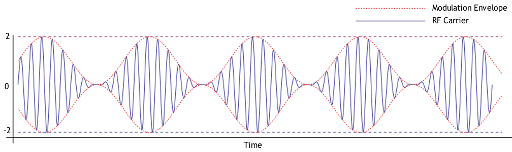
The modulation envelope is the smooth curve that connects the peaks of the modulated signal. When we demodulate an AM signal, what we get is a waveform that looks like the modulation envelope. The figure below shows an amplitude modulated signal and the modulation envelope.


An amplitude-modulated carrier.

QUESTION: What type of modulation varies the instantaneous power level of the RF signal? (G8A05)
ANSWER: Amplitude modulation

QUESTION: What is the modulation envelope of an AM signal? (G8A11)
ANSWER: The waveform created by connecting the peak values of the modulated signal


Single sideband, or SSB, is a type of amplitude modulation. A conventional AM signal has three components, the carrier and two sidebands. Since the carrier signal carries no information and the information in both sidebands is the same, someone figured out that by eliminating the carrier and one of the sidebands you could still transfer the same amount of information.

One of the advantage of SSB voice communications is that it has a narrower bandwidth than AM, FM, or phase modulation. An AM signal requires a bandwidth of 6 kHz or more, and an FM signal can require up to 15 kHz, but a single sideband signal takes up a bandwidth of only 3 kHz.

QUESTION: Which of the following phone emissions uses the narrowest bandwidth? (G8A07)
ANSWER: Single sideband.

You must be careful when setting the audio level used to modulate an AM or SSB phone signal. If you set the level too high, the signal will be over-modulated, and this may cause your signal to be distorted due to “flat-topping.” It can also cause your signal to take up more bandwidth than is allowed.

QUESTION: What is meant by the term “flat-topping,” when referring to a single sideband phone transmission? (G8A10)
ANSWER: Signal distortion caused by excessive drive

QUESTION: Which of the following is an effect of overmodulation? (G8A08)
ANSWER: Excessive bandwidth.

Another type of modulation that we use in amateur radio is frequency modulation, or FM. In an FM signal, the carrier frequency changes proportionally to the instantaneous amplitude of the modulating signal. Most VHF and UHF repeaters use frequency modulation.

QUESTION: What is the name of the process that changes the instantaneous frequency of an RF wave to convey information? (G8A03)
ANSWER: Frequency modulation

Another way to produce a frequency-modulated signal is to use phase modulation (PM). As the name implies, to produce a phase modulated signal, the modulator changes the phase angle of the signal. The modulator used to produce a PM signal is a reactance modulator. Changes in reactance cause a phase shift in the output signal.

QUESTION: What is the name of the process that changes the phase angle of an RF signal to convey information? (G8A02)
ANSWER: Phase modulation

QUESTION: What emission is produced by a reactance modulator connected to a transmitter RF amplifier stage? (G8A04)
ANSWER: Phase modulation

Some modes, such as radio teletype (RTTY) use a modulation method called frequency-shift keying, or FSK. An RTTY signal is a digital signal consisting of “marks” and “spaces.” A mark is sent at one frequency, and the space at another. The RTTY signal, therefore, alternates between one and the other.

QUESTION: How is an FSK signal generated? (G8A01)
ANSWER: By changing an oscillator’s frequency directly with a digital control signal

Another way to send digital information is by using phase-shift keying (PSK). When you send a PSK signal, you’re changing the phase of the modulation, not the frequency of the modulated signal. In a binary phase-shift keying, or BPSK, signal you shift the phase 180 degrees to send a one or a zero.

Some phase-shift keying methods, however, let you send more than one bit at a time. Quadrature phase-shift keying, or QPSK, for example, allows you to send two bits at a time. It does this by allowing more phase-shift options than BPSK. A BPSK signal will only shift 180 degrees, either plus or minus. A QPSK signal, however can shift 45, 135, 225, or 315 degrees. Using QPSK allows you to send data faster than you can with BPSK, but the cost is a slightly higher bandwidth.

QUESTION: Which of the following is characteristic of QPSK31? (G8A06)
ANSWER: The bandwidth is slightly higher than BPSK31

One of the most popular new digital modes is FT8. FT8 get its name from the fact that it was developed by Frankie and Joe Taylor, K1JT, and uses eight-tone frequency shift keying modulation. To operate FT8, you use the WSJT software, which uses some very sophisticated digital processing to allow it to receive very weak signals with low signal-to-noise ratios.

QUESTION: What type of modulation is used by the FT8 digital mode? (G8A09)
ANSWER: 8-tone frequency shift keying

QUESTION: Which of the following narrow-band digital modes can receive signals with very low signal-to-noise ratios? (G8A12)
ANSWER: FT8


Frequency mixing, multiplication, bandwidths of various modes, deviation; duty cycle

One of the most important circuits found in amateur radio equipment is the mixer. A mixer takes two input signals and outputs the sum and difference of the two input signals. This process is called heterodyning.

QUESTION: What is another term for the mixing of two RF signals? (G8B03)
ANSWER: Heterodyning

QUESTION: What combination of a mixer’s Local Oscillator (LO) and RF input frequencies is found in the output? (G8B11)
ANSWER: The sum and difference

In a superheterodyne receiver, the amplified signal from the antenna is combined with the signal from a circuit called the local oscillator to produce a signal at an intermediate frequency, or IF. When you tune the radio, you’re actually changing the frequency of the local oscillator.

To see how this might work, consider this simple example. Say you want to receive a signal on 14.250 MHz, and the IF of your receiver is 455 kHz. You would then tune the local oscillator to 13.795 MHz because 14.250 – 13.795 MHz = 455 kHz. To tune the receiver to 14.240 MHz, you’d set the local oscillator to 13.785 MHz.

QUESTION: Which mixer input is varied or tuned to convert signals of different frequencies to an intermediate frequency (IF)? (G8B01)
ANSWER: Local oscillator

One problem with simple superheterodyne receivers is that two different frequencies will actually produce a 455 kHz mixer output because the mixer outputs both the sum and the difference of the two input frequencies. Say that you tune your local oscillator to 13.800 MHz to receive a 14.255 MHz signal. If your receiver does not have good input filtering, then a signal at 13.345 MHz will also produce a 455 kHz mixer output and you could hear signals on both frequencies simultaneously. We call this type of behavior an image response.

QUESTION: If a receiver mixes a 13.800 MHz VFO with a 14.255 MHz received signal to produce a 455 kHz intermediate frequency (IF) signal, what type of interference will a 13.345 MHz signal produce in the receiver? (G8B02)
ANSWER: Image response

Another thing that can happen is that the mixer does not operate in a linear fashion. When this happens, the two signals at the input of the mixer can produce outputs at random frequencies. This is called intermodulation, or simply “intermod.” This can happen in any non-linear circuit or connection.

QUESTION: What process combines two signals in a non-linear circuit or connection to produce unwanted spurious outputs? (G8B12)
ANSWER: Intermodulation

FM transmitters use multipliers to produce a VHF signal. They often generate an FM signal in the 12 MHz range and then multiply that signal by 12 to output a signal in the 2 m band (144- 148 MHz).

QUESTION: What is the stage in a VHF FM transmitter that generates a harmonic of a lower frequency signal to reach the desired operating frequency? (G8B04)
ANSWER: Multiplier

When modulating the 12 MHz signal, you must use a proportionally smaller deviation if you plan to multiply that signal to the 2 m band. If you are going to multiply the 12 MHz signal 12 times, then the deviation must be 1/12 of the deviation when transmitting in the 2 m band.

QUESTION: What is the frequency deviation for a 12.21 MHz reactance modulated oscillator in a 5 kHz deviation, 146.52 MHz FM phone transmitter? (G8B07)
ANSWER: 416.7 Hz

5 kHz x 1/12 = 416.7 kHz

FM phone is often used on the VHF and UHF bands, but not below 29.5 MHz because it requires a fair amount of bandwidth. The equation for calculating the bandwidth of an FM signal is:

BW=2(Δf+fm)

where Δf = deviation, BW = total bandwidth (for 98% power), and fm = modulating frequency.

QUESTION: What is the total bandwidth of an FM phone transmission having 5 kHz deviation and 3 kHz modulating frequency? (G8B06)
ANSWER: 16 kHz

“Digital modes,” such as PACTOR-III, are getting more popular on the HF bands. The bandwidth of a PACTOR-III is about the same as an SSB signal, or 2300 Hz.

QUESTION: What is the approximate bandwidth of a PACTOR-III signal at maximum data rate? (G8B05)
ANSWER: 2300 Hz

In general, digital modes have much higher duty cycles than the traditional HF modes, such as CW or SSB. It is important to know this because most transmitters used in amateur radio are not designed to be operated at 100% duty cycle. That is to say that they may be capable of outputting 100 W, but not continuously for an extended time.

QUESTION: Why is it important to know the duty cycle of the mode you are using when transmitting? (G8B08)
ANSWER: Some modes have high duty cycles which could exceed the transmitter’s average power rating

It’s also important to know the symbol rate of the digital mode that you’re operating. The reason for this is that digital modes that transfer data at a high rate need more bandwidth than modes that send data at a slower rate.

QUESTION: What is the relationship between transmitted symbol rate and bandwidth? (G8B10)
ANSWER: Higher symbol rates require higher bandwidth

Noise can be a problem when operating digital modes because noise can cause errors, and many of these digital modes do not have error correction. One way to minimize the effects of noise is to use filters to filter out the noise and to adjust your receiver’s bandwidth so that it only passes the signal that you’re interested in. This is also true for modes other than digital modes, such as CW or SSB.

QUESTION: Why is it good to match receiver bandwidth to the bandwidth of the operating mode? (G8B09)
ANSWER: It results in the best signal to noise ratio

Digital emission modes

Digital modes have become very popular in amateur radio. To use the digital modes, you connect a computer to your radio, and a computer program then encodes and decodes the digital signal.

PSK 31 is one of the more popular digital mode on the HF bands. It’s called PSK31 because the transmitted symbol rate is approximately 31 baud. That’s pretty slow, but it is about as fast as a person can type. In addition, its bandwidth is approximately 31 Hz.

QUESTION: What does the number 31 represent in “PSK31”? (G8C09)
ANSWER: The approximate transmitted symbol rate

PSK31 can be a very efficient mode. One reason for this is that it encodes characters with a type of code called Varicode. It is called Varicode because the number of data bits sent in a single PSK31 character varies. More frequently used characters use fewer bits, while less frequently used characters, such as upper case letters, use more bits.

QUESTION: Which type of code is used for sending characters in a PSK31 signal? (G8C12)
ANSWER: Varicode

QUESTION: Which of the following statements is true about PSK31? (G8C08)
ANSWER: Upper case letters use longer Varicode symnbols and thus slow down transmission

Another popular digital mode is radio teletype, or RTTY. In the past, we used clunky, mechanical teletype machines to send and receive RTTY, but now most amateurs use a computer to operate this mode.

RTTY uses the Baudot code, which is really a pretty ancient code. It only uses five bits per character, meaning that to send letters, numbers, and punctuation, you have to shift between two different sets of characters.

QUESTION: Which of the following describes Baudot code? (G8C04)
ANSWER: A 5-bit code with additional start and stop bits

RTTY uses frequency-shift keying to send the ones and zeroes. One frequency is interpreted as a one, or “mark.” The other frequency is interpreted as a zero or “space.”

QUESTION: How are the two separate frequencies of a Frequency Shift Keyed (FSK) signal identified? (G8C11)
ANSWER: Mark and space

PSK31 and RTTY are “general purpose” modes. That is to say that they are used by amateurs for ragchewing, contesting, DXing, and other activities. One digital mode that is more specialized in nature is Weak Signal Propagation Reporter, or WSPR for short. WSPR is design to find potential propagation paths with low-power transmissions. Transmissions carry a station’s callsign, Maidenhead grid locator, and transmitter power in dBm. The program used to receive WSPR signals can decode signals with signal-to-noise ratios as low as −28 dB. Stations with internet access can automatically upload their reception reports to a central database called WSPRnet, which displays the paths over which signals are being received.

QUESTION: Which digital mode is used as a low-power beacon for assessing HF propagation? (G8C02)
ANSWER: WSPR

Packet radio is a form of digital switching technology used by several different digital modes, including APRS and PACTOR. In packet radio, data transmitted from one station to another are bundled up in packets. In addition to the actual data, a packet contains a header, which tells computers along the way how to handle and route the packet.

QUESTION: What part of a packet radio frame contains the routing and handling information? (G8C03)
ANSWER: Header


PACTOR is a particularly robust mode that uses packet radio technology to extend Internet functionality to remote users via amateur radio. The reason amateurs use PACTOR is that it can detect data errors and request that packets be resent. There is a limit, however. If the radio link is poor, and too many retransmissions are requested, the two stations will simply stop trying.

QUESTION: In the PACTOR protocol, what is meant by an NAK response to a transmitted packet? (G8C05)
ANSWER: The receiver is requesting the packet be retransmitted

QUESTION: What action results from a failure to exchange information due to excessive transmission attempts when using PACTOR or WINMOR? (G8C06)
ANSWER: The connection is dropped


Another method for controlling errors when sending and receiving data packets is called Automatic Repeat Request, or ARQ.

QUESTION: How does the receiving station respond to an ARQ data mode packet containing errors? (G8C07)
ANSWER: Requests the packet be retransmitted

Some digital modes, such as FreeDV use what’s called forward error correction, which allows the receiving station to not only detect errors in a data packet, but also to correct them. It does this by sending redundant data. The obvious disadvantage of this approach is that it is slower than other data modes because redundant data needs to be sent.

QUESTION: How does forward error correction (FEC) allow the receiver to correct errors in received data packets? (G8C10)
ANSWER: By transmitting redundant information with the data

To operate most digital modes, you use software that supports that particular mode. For example, to operate PSK31, you might use a program called fldigi. To operate FT8, you use a program called WSJT. One thing that these programs have in common is that they display the signals they are receiving in what’s called a waterfall display.

The waterfall display is a time record of the intensity of signals over a range of frequencies. Waterfall displays are really pretty cool. You get a quick indication of the activity on a band and can quickly tune in stations that you want to contact. Waterfall displays can also give you an indication of the quality of the signals that you’re receiving. You can, for example, quickly see if a station is overmodulating.

QUESTION: Which of the following describes a waterfall display? (G8C14)
ANSWER: Frequency is horizontal, signal strength is intensity, time is vertical

QUESTION: What is indicated on a waterfall display by one or more vertical lines on either side of a digital signal? (G8C13)
ANSWER: Overmodulation

On some bands, amateurs share frequencies with other services. For example, some 2.4 GHz WiFi frequencies actually fall within the amateur radio band. As a result, amateurs are able to use commercial WiFi equipment, but are not encumbered by some of the restrictions on that equipment. For example, if you really wanted to, you could operate with high power and directional antennas to allow you to set up some very wide area networks. In fact, some amateur radio operators do this.

QUESTION: On what band do amateurs share channels with the unlicensed Wi-Fi service? (G8C01)
ANSWER: 2.4 GHz

Filed Under: Books and Magazines, Classes/Testing/Licensing

2019 No Nonsense General Class Study Guide: Practical Circuits

February 11, 2019 By Dan KB6NU 4 Comments

As always, comments are appreciated. I especially had some trouble distilling the explanation of questions on software-defined radio. There were three questions added on this topic to the question pool…..Dan


Power supplies; schematic symbols

Power supplies are devices that convert AC power to the DC voltages needed to power amateur radio equipment. There are two main types of power supplies available: linear power supplies and switching power supplies.

Linear supplies use a transformer to transform the voltage up or down, a rectifier to convert the AC voltage to a DC voltage, and capacitors and inductors to smooth the output voltage. The rectifier in a linear supply may be a half-wave rectifier, a full-wave rectifier, or a bridge rectifier.

As the name implies a half-wave rectifier converts half, or 180 degrees, of an AC cycle to DC, while a full-wave rectifier converts all 360 degrees of the cycle to AC. The bridge rectifier also converts the complete cycle to DC.

QUESTION: What portion of the AC cycle is converted to DC by a half-wave rectifier? (G7A05)
ANSWER: 180 degrees

QUESTION: What portion of the AC cycle is converted to DC by a full-wave rectifier? (G7A06)
ANSWER: 360 degrees

Each type of rectifier has its advantages and disadvantages. A half-wave rectifier uses only a single diode, but only converts half the AC power available into DC. A full-wave rectifier converts the entire AC power available into DC, but requires a center-tapped transformer. A bridge rectifier does not require the use of a more expensive center-tapped transformer, but needs four diodes.

QUESTION: What is an advantage of a half-wave rectifier in a power supply? (G7A04)
ANSWER: Only one diode is required

QUESTION: Which type of rectifier circuit uses two diodes and a center-tapped transformer? (G7A03)
ANSWER: Full-wave

The output of an unfiltered rectifier circuit is a series of DC pulses. For the half-wave rectifier, the frequency of the pulses is the same as the AC input, as there is an output only when the AC input goes positive. For the full-wave rectifier, the output frequency is twice that, as it outputs a pulse when the AC goes positive and negative.

QUESTION: What is the output waveform of an unfiltered full-wave rectifier connected to a resistive load? (G7A07)
ANSWER: A series of DC pulses at twice the frequency of the AC input

The output of a rectifier connects to a filter made up of capacitors and inductors. The purpose of this filter is to filter out the AC component of the pulsed DC and output a steady DC voltage.

QUESTION: Which of the following components are used in a power supply filter network? (G7A02)
ANSWER: Capacitors and inductors

A component often found across the output of a power supply is a power-supply bleeder resistor. The purpose of this resistor is to discharge, or bleed off, the charge on the filter capacitors when the power supply is turned off. The value of this resistor is normally a very high value so that very little current flow through it during normal operation.

QUESTION: What useful feature does a power supply bleeder resistor provide? (G7A01)
ANSWER: It ensures that the filter capacitors are discharged when power is removed


Switching, or switched-mode power supplies are now being sold by many vendors. Switching supplies are smaller and lighter than linear supplies, but the circuits are much more complex than linear power supply circuits.

QUESTION: Which of the following is an advantage of a switchmode power supply as compared to a linear power supply? (G7A08)
ANSWER: High frequency operation allows the use of smaller components


When designing or troubleshooting radios, amateur radio operators use schematic diagrams to describe circuits. Various symbols represent the different types of components. A typical schematic is shown in Figure G7-1.

QUESTION: Which symbol in figure G7-1 represents a field effect transistor? (G7A09)
ANSWER: Symbol 1

QUESTION: Which symbol in figure G7-1 represents a Zener diode? (G7A10)
ANSWER: Symbol 5

QUESTION: Which symbol in figure G7-1 represents an NPN junction transistor? (G7A11)
ANSWER: Symbol 2

QUESTION: Which symbol in Figure G7-1 represents a solid core transformer? (G7A12)
ANSWER: Symbol 6

QUESTION: Which symbol in Figure G7-1 represents a tapped inductor? (G7A13)
ANSWER: Symbol 7

Digital circuits

Digital circuits are circuits whose output are one of two voltages—either “on” or “off,” “high” or “low,” “one” or “zero.” Digital circuits use the binary system to represent numbers because each of the digits in a binary number is either a 1 or a 0.

We use digital circuits to implement logic functions, and we call a circuit that implements a logic function a “gate.” Two typical logic functions are AND and NOR. The output of an AND gate is 1 when all of the inputs are 1. The output of a NOR gate is 1 only when both inputs are 0.

QUESTION: Which of the following describes the function of a two-input AND gate? (G7B03)
ANSWER: Output is high only when both inputs are high

QUESTION: Which of the following describes the function of a two input NOR gate? (G7B04)
ANSWER: Output is low when either or both inputs are high

Integrated circuits that provide more complex logic functions, such as flip-flops, counters and shift registers, are also available. As the name implies, a counter counts input pulses and outputs the count in binary. The figure below shows a three-bit counter made with 3 D flip-flops. A D flip-flop is a circuit whose output, Q, changes when it receives a clock pulse. After the clock pulse, Q is equal to D. The other output, Q[bar] is the inverse of Q.

A three-bit counter has eight output states.

QUESTION: How many states does a 3-bit binary counter have? (G7B05)
ANSWER: 8

A shift register consists of an array of flip flops whose outputs are connected to the input of the next flip-flop in the chain. When the shift register receives a clock pulse, data is shifted down the array.

QUESTION: What is a shift register? (G7B06)
ANSWER: A clocked array of circuits that passes data in steps along the array

Oscillators and amplifiers

An oscillator is a circuit that generates an AC output signal. It normally consists of an amplifier, part of whose output is fed back to the input through a filter. This feedback keeps the circuit oscillating, while the filter determines the frequency of the oscillation.

QUESTION: Which of the following are basic components of a sine wave oscillator? (G7B07)
ANSWER: A filter and an amplifier operating in a feedback loop

An “LC” oscillator uses an inductor and a capacitor connected so that they form what’s called a tank circuit to provide feedback. The tank circuit is the filter that determines the frequency of oscillation.

QUESTION: What determines the frequency of an LC oscillator? (G7B09)
ANSWER: The inductance and capacitance in the tank circuit

There are many different types of amplifiers. These types are often categorized by class: Class A, Class B, Class C, and Class D amplifiers. Each class of amplifiers has certain characteristics. Linear amplifiers, for example, are usually Class A amplifiers. Class A amplifiers add very little distortion and the output waveform is very close to the input waveform, just larger. This makes them the best choice for amplifying AM and SSB phone signals.

QUESTION: Which of the following describes a linear amplifier? (G7B10)
ANSWER: An amplifier in which the output preserves the input waveform

The Class C amplifier, on the other hand, is not linear. Fortunately, an amplifier need not be linear to amplify FM and CW signals. They are a good choice for FM and CW because they are more efficient than Class A, Class B, and Class AB amplifiers.

QUESTION: Which of these classes of amplifiers has the highest efficiency? (G7B02)
ANSWER: Class C

QUESTION: For which of the following modes is a Class C power stage appropriate for amplifying a modulated signal? (G7B11)
ANSWER: FM

QUESTION: How is the efficiency of an RF power amplifier determined? (G7B08)
ANSWER: Divide the RF output power by the DC input power

High-power amplifiers are often prone to self-oscillation due to stray capacitive feedback. To prevent this from happening, you induce some feedback that is out of phase with the stray capacitive feedback to neutralize it.

QUESTION: What is the reason for neutralizing the final amplifier stage of a transmitter? (G7B01)
ANSWER: To eliminate self-oscillations

Receivers and transmitters, filters, oscillators

Filters are very important circuits in amateur radio equipment. As the name implies, these circuits are used to clarify or process radio signals. For example, one type of filter—a low-pass filter—passes all signals whose frequencies are below a certain frequency, called the “cutoff frequency.”

QUESTION: What is the frequency above which a low-pass filter’s output power is less than half the input power? (G7C12)
ANSWER: Cutoff frequency

One application of a low-pass filter is to block the VHF and UHF harmonics produced by an amateur transceiver from reaching the antenna. To do this, you would connect the input of the filter to the output of your transceiver and the output of the filter to your antenna system.

QUESTION: What should be the impedance of a low-pass filter as compared to the impedance of the transmission line into which it is inserted? (G7C06)
ANSWER: About the same

Band-pass filters are designed to pass signals between two frequencies—called the passband—while rejecting signals outside this range. The width of this frequency range is the difference between the two frequencies at which the signal power is one-half the maximum power. The difference between the upper and lower half-power frequencies is called the bandwidth of the filter.

QUESTION: The bandwidth of a band-pass filter is measured between what two frequencies? (G7C14)
ANSWER: Upper and lower half-power

How well a filter rejects signals outside the passband is called ultimate rejection.

QUESTION: What term specifies a filter’s maximum ability to reject signals outside its passband? (G7C13)
ANSWER: Ultimate rejection

Of course, filters aren’t perfect. They will reduce, or attenuate, the input signal level of the input signal, by some amount, even if the signal is within the passband.

QUESTION: What term specifies a filter’s attenuation inside its passband? (G7C15)
ANSWER: Insertion loss


Filters are also used in amateur radio transmitters. For example, to produce a single sideband signal, you combine the audio signal and the signal from the carrier oscillator in a balanced modulator. The output of the balanced modulator includes both the upper and lower sidebands. To obtain a single sideband, you filter out the sideband you don’t want.

QUESTION: Which circuit is used to combine signals from the carrier oscillator and speech amplifier then send the result to the filter in some single sideband phone transmitters? (G7C02)
ANSWER: Balanced modulator

QUESTION: Which of the following is used to process signals from the balanced modulator then send them to the mixer in some single sideband phone transmitters? (G7C01)
ANSWER: Filter

For many years, the superheterodyne receiver has been the most popular type of amateur radio receiver. Superheterodyne receivers convert the received signal to an intermediate frequency (IF), using a circuit called a mixer. The mixer combines the incoming signal with the signal from an HF oscillator, called the local oscillator, to produce the IF signal. In some SSB receivers, a product detector then demodulates that IF signal.

QUESTION: What circuit is used to process signals from the RF amplifier and local oscillator then send the result to the IF filter in a superheterodyne receiver? (G7C03)
ANSWER: Mixer

QUESTION: What circuit is used to combine signals from the IF amplifier and BFO and send the result to the AF amplifier in some single sideband receivers? (G7C04)
ANSWER: Product detector

QUESTION: What is the simplest combination of stages that implement a superheterodyne receiver? (G7C07)
ANSWER: HF oscillator, mixer, detector

FM receivers have different types of circuits than the superheterodyne receivers designed for AM, CW, and SSB reception. In FM receivers, the detector is called a discriminator.

QUESTION: What circuit is used in analog FM receivers to convert IF output signals to audio? (G7C08)
ANSWER: Discriminator

Most modern transceivers use circuits called a direct digital synthesizer to control the receive and transmit frequencies. This gives them much more stability than receivers that use analog local oscillators.

QUESTION: Which of the following is a typical application for a Direct Digital Synthesizer? (G7C16)
ANSWER: A high-stability variable frequency oscillator in a transceiver

QUESTION: Which of the following is an advantage of a direct digital synthesizer (DDS)? (G7C05)
ANSWER: Variable frequency with the stability of a crystal oscillator

Digital techniques have proven to be so effective at generating and receiving radio signals, that some transceivers now implement most functions using digital signal processors. We even have a special term for this type of radio: software defined radio, or SDR.

QUESTION: What is meant by the term “software-defined radio” (SDR)? (G7C11)
ANSWER: A radio in which most major signal processing functions are performed by software

Software-defined radios work with two signals, called I (in phase) and Q (quadrature), that are 90 degrees out of phase. When an SDR is receiving, the receiver’s analog-to-digital converters convert the incoming signal into a series of values, representing the I and Q signals. When an SDR is transmitting, it does the reverse. It uses the digital representations of the I and Q signals to produce an RF output.

QUESTION: What is the phase difference between the I and Q signals that software-defined radio (SDR) equipment uses for modulation and demodulation? (G7C09)
ANSWER: 90 degrees

QUESTION: What is an advantage of using I and Q signals in software-defined radios (SDRs)? (G7C10)
ANSWER: All types of modulation can be created with appropriate processing

Filed Under: Books and Magazines, Classes/Testing/Licensing

2019 General Class study guide: Electrical principles

February 4, 2019 By Dan KB6NU 4 Comments

The 2019 question pool is out, and I’ve started updating the No Nonsense General Class Study Guide. Here’s the first chapter. As always, comments are welcome…Dan


Reactance; inductance; capacitance; impedance; impedance matching

When an alternating current (AC) is applied to capacitors and inductors, they oppose the flow of current, but in a more complex way than the way resistors oppose the flow of direct current. The opposition to alternating currents by capacitors and inductors is called reactance, and we use the letter X to stand for reactance. The unit of reactance is the ohm.

QUESTION: What is reactance? (G5A02)

ANSWER: Opposition to the flow of alternating current caused by capacitance or inductance

QUESTION: What unit is used to measure reactance? (G5A09)

ANSWER: Ohm

QUESTION: Which of the following causes opposition to the flow of alternating current in an inductor? (G5A03)

ANSWER: Reactance

QUESTION: Which of the following causes opposition to the flow of alternating current in a capacitor? (G5A04)

ANSWER: Reactance

The reactance caused by a capacitor or inductor depends on the frequency of the AC source. You calculate the reactance caused by an inductor with the equation:

XL = 2πfL

where XL is the inductive reactance in ohms (Ω), f is the frequency of the AC applied to the inductor in Hertz (Hz), and L is the inductance in henries. As you can see, as the frequency of the AC increases, so does the reactance of the inductor.

QUESTION: How does an inductor react to AC? (G5A05)

ANSWER: As the frequency of the applied AC increases, the reactance increases

You calculate the reactance caused by a capacitor with the equation:

XC = 1/(2πfC)

where XC is the capacitive reactance in ohms (Ω), f is the frequency of the AC applied to the capacitor in Hertz (Hz), and C is the capacitance in farads. As you can see from the equation, as the frequency of the AC increases, the capacitive reactance decreases.

QUESTION: How does a capacitor react to AC? (G5A06)

ANSWER: As the frequency of the applied AC increases, the reactance decreases

Resistors also oppose the flow of current in an AC circuit. When an AC circuit contains both resistance and reactance, the resistance and reactance combine in a complex way to oppose the flow of current in the circuit. We call this combination impedance, and impedance is measured in ohms.

QUESTION: What is impedance? (G5A01)

ANSWER: The opposition to the flow of current in an AC circuit

When setting up an amateur radio station, it is important to know the input and output impedances of devices and circuits that you will connect together. When these two impedances are equal, they are said to “match” one another. For example, when the output impedance of a transmitter is 50 ohms and the input impedance of an antenna is 50 ohms, they match one another.

If the output impedance of a circuit or device (often called the “source”) does not match the input impedance of the circuit or device that you connect to it (often called the “load”), the source will not deliver the maximum amount of power to the load. Impedance matching is, therefore, important so the source can deliver maximum power to the load.

QUESTION: What happens when the impedance of an electrical load is equal to the output impedance of a power source, assuming both impedances are resistive? (G5A07)

ANSWER: The source can deliver maximum power to the load

Impedance matching is so important that engineers have devised several different types of circuits and devices to match the output impedance of a source to the input impedance of a load. One way to do this is to insert an LC network, which is a circuit made up of inductors (L) and capacitors (C), between the source and the load. You could also use an impedance-matching transformer or a length of transmission line.

QUESTION: What is one reason to use an impedance matching transformer? (G5A08)

ANSWER: To maximize the transfer of power

QUESTION: Which of the following devices can be used for impedance matching at radio frequencies? (G5A10)

ANSWER: All these choices are correct

  • A transformer
  • A Pi-network
  • A length of transmission line

QUESTION: Which of the following describes one method of impedance matching between two AC circuits? (G5A11)

ANSWER: Insert an LC network between the two circuits

The Decibel; current and voltage dividers; electrical power calculations; sine wave root-mean-square (RMS) values; PEP calculations

Kirchoff’s Current Law states that the sum of currents entering a circuit node must equal the sum of the currents leaving the node. In the circuit below, we have a parallel circuit made up of two resistors. In this circuit, I = I1 + I2, or to put it another way, the total current entering a parallel circuit equals the sum of the currents through each branch, or in this case, the sum of the currents thought each resistor.

QUESTION: How does the total current relate to the individual currents in each branch of a purely resistive parallel circuit? (G5B02)

ANSWER: It equals the sum of the currents through each branch

In amateur radio, we have to deal with AC voltages and currents all the time. AC powers our radios in our base stations and radio signals are AC signals, and especially sinusoidal signals, that is signals that look like sine waves. A sine wave is shown in the figure below.

Three important parameters of a sinusoidal AC signal are:

  • The peak value, Vp, which is the highest voltage value.

  • The peak-to-peak value, which is the difference between the highest value and the lowest value. In a sine wave, Vp-p is twice the value of Vp.

  • The root mean square, or RMS value, VRMS. The RMS value is the voltage that causes the same power dissipation as a DC voltage of the same value. For an AC sinusoidal signal, the RMS value is .707 times the peak value.

QUESTION: What value of an AC signal produces the same power dissipation in a resistor as a DC voltage of the same value? (G5B07)

ANSWER: The RMS value

QUESTION: What is the RMS voltage of a sine wave with a value of 17 volts peak? (G5B09)

ANSWER: 12 volts

VRMS = Vp x .707 = 17 V x .707 = 12 volts

You can also calculate the peak-to-peak voltage of an AC signal if you know the RMS value:

Vpeak = VRMS ÷ 0.707 = VRMS x 1.414

The peak to peak voltage, or Vp-p, is twice that value, or VRMS x 2.828.

QUESTION: What is the peak-to-peak voltage of a sine wave with an RMS voltage of 120.0 volts? (G5B08)

ANSWER: 339.4 volts

Vp-p = VRMS x 2.828 = 120 x 2.828 = 339.4 volts.

When the voltage and current are in phase, the power delivered by an AC signal is equal to the RMS voltage times the current, or

P (watts) = VRMS x I

Using Ohm’s Law, we can show that:

P = V2RMS / R

P = I2RMS x R

For DC circuits, the equations are:

P (watts) = V x I

P = V2/ R

P = I2 x R

Let’s look at some examples:

QUESTION: How many watts of electrical power are used if 400 VDC is supplied to an 800 ohm load? (G5B03)

ANSWER: 200 watts

P = V2/ R = 4002/800 = 160,000 / 800 = 200 watts

QUESTION: How many watts of electrical power are used by a 12 VDC light bulb that draws 0.2 amperes? (G5B04)

ANSWER: 2.4 watts

P = V x I = 12 x 0.2 = 2.4 watts

QUESTION: How many watts are dissipated when a current of 7.0 milliamperes flows through a 1250 ohm resistance? (G5B05)

ANSWER: Approximately 61 milliwatts

P = I2 x R = 0.0072 x 1,250 ≈ .061 W ≈ 61 milliwatts

These formulas can also be used to calculate RF power and RF voltages and currents.

QUESTION: What would be the RMS voltage across a 50 ohm dummy load dissipating 1200 watts? (G5B12)

ANSWER: 245 volts

V2RMS = P / R = 50 x 1,200 = 60,000, √60,000 ≈ 245 volts

A term sometimes used to describe the power output of a phone signal is peak envelope power (PEP). This is the maximum instantaneous power achieved when transmitting a phone signal. For an unmodulated carrier, the peak envelope power is equal to the average power. When transmitting a single sideband signal, though, the amplitude will vary with time, and the average power may be considerably less.

Here are some examples:

QUESTION: What is the ratio of peak envelope power to average power for an unmodulated carrier? (G5B11)

ANSWER: 1.00

QUESTION: What is the output PEP of an unmodulated carrier if an average reading wattmeter connected to the transmitter output indicates 1060 watts? (G5B13)

ANSWER: 1060 watts

QUESTION: What is the output PEP from a transmitter if an oscilloscope measures 200 volts peak-to-peak across a 50 ohm dummy load connected to the transmitter output? (G5B06)

ANSWER: 100 watts

VRMS = Vp x 0.707 = Vp-p/2 x 0.707 = 100 x 0.707 = 70.7 V

P = V2RMS ÷ R = 70.72 ÷ 50 = 100 watts

QUESTION: What is the output PEP from a transmitter if an oscilloscope measures 500 volts peak-to-peak across a 50 ohm resistive load connected to the transmitter output? (G5B14)

ANSWER: 625 watts

VRMS = Vp x 0.707 = Vp-p/2 x 0.707 = 250 V x 0.707 = 176.75 V

P = V2RMS ÷ R = 176.752 ÷ 50 = 625 watts

Often, we’re not concerned with the actual power, but with the ratio of power input to power output. For example, if an amplifier has a gain of 10, we know that if we input a 1 W signal, we’ll get 10 W out. Quite often, you’ll see this ratio specified in decibels, or dB.

The formula for calculating power ratios in dB is:

A(dB) = 10 x log10 (P2/P1)

Using this formula, you can see that a two-times increase or decrease in power results in a change of about 3 dB.

QUESTION: What dB change represents a factor of two increase or decrease in power? (G5B01)

ANSWER: Approximately 3 dB

A(dB) = 10 x log10 (P2/P1) = 10 x log10 (2/1) = 10 x .301 ≈ 3 dB

When P2/P1 is less than 1, it means there is a power loss.

QUESTION: What percentage of power loss would result from a transmission line loss of 1 dB? (G5B10)

ANSWER: 20.6 percent

P2/P1 = 10(A(dB)/10) = 10-0.11 = .794

Note that since this is a power loss, the value we use in the equation is -1 dB, and the power loss is 20.6% because P2/P1 is equal to 79.4%.

Resistors, capacitors, and inductors in series and parallel; transformers

Connecting components in series and in parallel will affect their effective values. For example, if you connect resistors in series, the effective resistance is the sum of the individual resistances.

QUESTION: Which of the following components increases the total resistance of a resistor? (G5C03)

ANSWER: A series resistor

IQUESTION: f three equal value resistors in series produce 450 ohms, what is the value of each resistor? (G5C05)

ANSWER: 150 ohms

If Rtotal = 450 ohms = 3 x R, then R = 450 ohms/3 = 150 ohms.

Connecting resistors in parallel will decrease the circuit resistance. The equation that you use to calculate the total resistance of resistors in parallel is:

Rtotal = 1/(1/R1 + 1/R2 + 1/R3…)

When the resistors are all equal, simply divide the value of one of the resistors by the number of resistors in parallel. Let’s look at some examples”

QUESTION: What is the total resistance of three 100 ohm resistors in parallel? (G5C04)

ANSWER: 33.3 ohms

Rtotal = 100 / 3 = 33.3 ohms

QUESTION: What is the total resistance of a 10 ohm, a 20 ohm, and a 50 ohm resistor connected in parallel? (G5C15)

ANSWER: 5.9 ohms

Rtotal = 1/(1/10 + 1/20 + 1/50) = 1/0.17 ≈ 5.9 ohms

Inductors work the same way as resistors. You would, therefore, add an inductor in series with an inductor to increase circuit inductance and connect inductors in parallel to decrease circuit inductance.

QUESTION: Which of the following components should be added to an inductor to increase the inductance? (G5C14)

ANSWER: An inductor in series

Here are a couple of examples:

QUESTION: What is the inductance of a 20 millihenry inductor connected in series with a 50 millihenry inductor? (G5C11)

ANSWER: 70 millihenrys,

QUESTION: What is the inductance of three 10 millihenry inductors connected in parallel? (G5C10)

ANSWER: 3.3 millihenrys

Capacitors, however, combine in the opposite way. You connect capacitors in parallel to increase the total capacitance. The equation that you use to calculate the total capacitance of two or more cpacitors in parallel is Ctotal = C1 + C2 + C3… Connecting capacitors in series decreases the total capacitance. The equation that you use to calculate the total capacitance of capacitors in series is Ctotal = 1/(1/C1 + 1/C2 + 1/C3…)

QUESTION: Which of the following components should be added to a capacitor to increase the capacitance? (G5C13)

ANSWER: A capacitor in parallel

QUESTION: What is the capacitance of a 20 microfarad capacitor connected in series with a 50 microfarad capacitor? (G5C12)

ANSWER: 14.3 microfarads

Ctotal = 1/(1/C1 + 1/C2) = 1/(1/20 + 1/50) = 1/.07 = 14.3 microfarads.

QUESTION: What is the capacitance of three 100 microfarad capacitors connected in series? (G5C09)

ANSWER: 33.3 microfarads

Ctotal = 1/(1/C1 + 1/C2 + 1/C3) = 1/(1/100 + 1/100 + 1/100) = 1/.03 = 33.3 microfarads. As you can see, if all the capacitors are equal, all you need to do is to divide the value of one of the capacitors by the number of capacitors in series, or in this case, Ctotal = 100 microfarads / 3 = 33.3 microfarads.

When working with capacitors, it’s important to take note of how the capacitance is specified. The capacitance is sometimes specified in microfarads (μF), sometimes in nanofarads (nF), and sometimes in picofarads (pF). A microfarad is 1,000 nanofarads, and a nanofarad is 1,000 picofarads. Here are a couple examples of how to convert between units:

QUESTION: What is the value in nanofarads (nF) of a 22,000 picofarad (pF) capacitor? (G5C17)

ANSWER: 22

QUESTION: What is the value in microfarads of a 4700 nanofarad (nF) capacitor? (G5C18)

ANSWER: 4.7

Where it’s really important to keep this in mind is when you’re working with some capacitors whose capacitance is specified in nanofarads and others who are specified in picofarads. For example,

QUESTION: What is the equivalent capacitance of two 5.0 nanofarad capacitors and one 750 picofarad capacitor connected in parallel? (G5C08)

ANSWER: 10.750 nanofarads

750 pF is equal to 0.75 nF, and because the capacitors are connected in parallel, the equivalent capacitance is equal to the sum of all the capacitances. Ctotal = C1 + C2 + C3 = 5 nF +5 nF + 0.75 nF = 10.750 nanofarads.

Inductors exhibit a behavior called mutual inductance. Mutual inductance occurs when a current flowing through one inductor induces a current in a nearby inductor. We use this behavior to create components called transformers. The simplest transformer has two windings: a primary winding and a secondary winding. When a current flows through a primary winding, it induces a current in the secondary winding and causes a voltage to appear across the secondary winding.

QUESTION: What causes a voltage to appear across the secondary winding of a transformer when an AC voltage source is connected across its primary winding? (G5C01)

ANSWER: Mutual inductance

The voltage across the secondary winding will be equal to the voltage across the primary times the ratio of the number of turns in the secondary to the number of turns in the primary. When the number of turns in the secondary winding is greater than the number of turns in the primary winding, the voltage across the secondary winding will be great than the voltage across the primary winding, and the transformer is called a step-up transformer.

When the number of turns in the secondary winding is less than the number of turns in the primary winding, the voltage across the secondary winding will be less than the voltage across the primary winding, and the transformer is called a step-down transformer.

QUESTION: What is the RMS voltage across a 500-turn secondary winding in a transformer if the 2250-turn primary is connected to 120 VAC? (G5C06)

ANSWER: 26.7 volts

Secondary voltage = primary voltage x primary turns/secondary turns = 120 V x 500/2250 = 120 x 0.222 = 26.7 V.

By reversing a transformer’s windings, that is connecting an input voltage to a transformer’s secondary winding and connecting the primary windings to the output circuit, you make a step-up transformer act like a step-down transformer and vice versa.

QUESTION: What happens if a signal is applied to the secondary winding of a 4:1 voltage step-down transformer instead of the primary winding? (G5C02)

ANSWER: The output voltage is multiplied by 4

Doing this is not necessarily a good idea, however. Current in the primary winding of a step-up transformer is higher than the current in the secondary, so the conductor of the primary winding of many voltage step-up transformers is larger in diameter than the conductor of the secondary winding. If you use a step-down transformer as a step-up transformer by connecting the input voltage to the secondary winding, the wire in the winding may not be able to handle the higher current and burn out.

QUESTION: Why is the conductor of the primary winding of many voltage step-up transformers larger in diameter than the conductor of the secondary winding? (G5C16)

ANSWER: To accommodate the higher current of the primary

Transformers are also used to transform impedances. The impedance ratio is also related to the turns ratio, but the transformation is equal to the square of the turns ratio. Here’s an example:

QUESTION: What is the turns ratio of a transformer used to match an audio amplifier having 600 ohm output impedance to a speaker having 4 ohm impedance? (G5C07)

ANSWER: 12.2 to 1

Turns ratio = √(output impedance/input impedance) = √150 = 12.2.


Filed Under: Books and Magazines, Classes/Testing/Licensing Tagged With: electrical principles, study guides

Restructuing ARRL dues

January 20, 2019 By Dan KB6NU 7 Comments

On reddit, someone recently brought up the lack of ARRL student dues. There is a $25 “youth membership,” but you have to jump through hoops to take advantage of it. The web page says,

Must be 21 years old or younger AND the oldest licensed Amateur in the household. Please call ARRL directly to join or renew under this level. 1-888-277-5289 (Toll-free US only) M-F 8am-5pm ET.

One commenter said, “I don’t get why you need to call them up for the youth rate, like why add this stupid step?” Another replied, “Yea, they’re really not that interested in youth.” It certainly seems that way, doesn’t it?

Overall, the ARRL really needs to take a look at its dues structure. Without question, the recent dues increase caused a lot of members to quit, and the current dues structure is not encouraging new members to join.

I’ve written in the past about how the ARRL needs to take a look at its life membership fees. And, there has been talk for ages about a “digital only” membership for those who don’t want to get a printed QST.

I think we may see some changes coming down the pipeline on dues, and maybe sooner than you think. The ARRL’s new CEO has the declining membership on his radar, and he mentioned this in his recent remarks at Ham Radio University. He also mentioned that the ARRL would be looking at new ways to deliver QST and its other publications to its members. Stay tuned.

Filed Under: ARRL, Books and Magazines

  • « Go to Previous Page
  • Page 1
  • Interim pages omitted …
  • Page 3
  • Page 4
  • Page 5
  • Page 6
  • Page 7
  • Interim pages omitted …
  • Page 18
  • Go to Next Page »

Primary Sidebar

No Nonsense Technician Class License Study Guide (for tests given between July 2026 and June 2030)

New No Nonsense Technican Class Study Guide now available!

The 2026 version of my Tech Class study guide is now available, and as always, the PDF version is FREE!. The ePub version costs $11.97, and a Kindle version and paperback version will be available on Amazon shortly.

Click here to get all of my "No Nonsense" study guides.

Also available: The CW Geek's Guide to Having Fun with Morse Code

W5SWL.Com
Retevis Ailunce H1 DMR Radio
DXpander: Cobweb antennas, Laser Cutting

You’ve got mail!

Enter your email address below and get an email every time I publish a new post.

Email


I frequently teach classes to help newcomers get their licenses. The next class will take place on Saturday, October 10, 2026 on the University of Michigan campus. Click here for more information.

If you can't make the class, subscribe to the mailing list to be notified of when the next class will be held.

You can always download my free study guide, and if you have any questions about the classes, or amateur radio in general, please feel free to email me directly.

Support KB6NU.Com

Donate $7.30 and get two of these cool stickers. Measuring 4.25-in. W by 2.75-in. H, it's perfect for your car, your shack, or wherever!

Contact me

If you have a question or comment about one of my blog posts, or a question about any of the material in my study guides, or just a question about ham radio in general, you can email me at [email protected].

Blogs You Should Also Read

  • AE5X: A CW-centric blog from Kingswood, Texas
  • K0LWC Blog
  • LA3ZA Ham Radio Blog
  • Little Radios, Big Fun – WB3GCK
  • Mr. Vacuum Tube's Blog
  • Radio Artisan – K3NG
  • The K0NR Weblog
  • VE3WDM's QRP Ham Radio Blog
  • W2LJ’s Blog

Ham Radio Websites

  • Dashtoons – The Hammin' Comedy by Jeff K1NSS

Podcasts

  • ICQ Podcast
  • Linux in the Ham Schack
  • No Nonsense Amateur Radio Podcast
  • Resonant Frequency Amateur Radio Podcast

Recent Comments

  • Bulin 47 AI on ICQPodcast Episode 485 – World Cup Special Event Station
  • Jesse Alexander on What do you think of this artwork for the ham radio EMF Explorer
  • CADProps on My first go at 3D printing not quite a success
  • Dan KB6NU on A Media Guide to Amateur Radio
  • Steve Stroh N8GNJ on A Media Guide to Amateur Radio

Meta

  • Log in
  • Entries feed
  • Comments feed
  • WordPress.org

Footer

Copyright © 2026 Daniel M. Romanchik, KB6NU · Log in