• Skip to primary navigation
  • Skip to main content
  • Skip to primary sidebar
  • Skip to footer

KB6NU's Ham Radio Blog

KB6NU's Ham Radio Blog
  • HOME
  • Study Guides
  • Teach a One-Day Tech Class
  • W8SRC Repeater Guide
  • Advertise
  • Hire Me

2020 Extra Class Study Guide

2020 Extra Class study guide: E9F – Transmission lines: characteristics of open and shorted feed lines; coax versus open-wire; velocity factor; electrical length; coaxial cable dielectrics

March 12, 2020 By Dan KB6NU 2 Comments

When setting up your amateur radio station, it’s important to know the characteristics of the feed lines you use in your antenna system. For example, did you know that the physical length of a coaxial cable transmission line is shorter than its electrical length? The reason for this is that electrical signals move more slowly in a coaxial cable than in air.

QUESTION: Why is the physical length of a coaxial cable transmission line shorter than its electrical length? (E9F03)
ANSWER: Electrical signals move more slowly in a coaxial cable than in air

The term we use to quantify the difference in how fast a wave travels in air versus how fast it travels in a feedline is velocity factor. The velocity factor of a transmission line is the velocity of the wave in the transmission line divided by the velocity of light in a vacuum. The dielectric materials used in the transmission line is one of the biggest factors that determine the velocity factor of a transmission line.

QUESTION: What is the velocity factor of a transmission line? (E9F01)
ANSWER: The velocity of the wave in the transmission line divided by the velocity of light in a vacuum

QUESTION: Which of the following has the biggest effect on the velocity factor of a transmission line? (E9F02)
ANSWER: Dielectric materials used in the line

Here are some typical velocity factors:

  • Solid polyethylene dielectric coaxial transmission line: 0.66
  • Foam polyethylene dielectric coaxial transmission line: 0.8
  • Air-insulated, parallel-conductor, or open-wire, feedline: 0.98

QUESTION: What is the approximate physical length of a solid polyethylene dielectric coaxial transmission line that is electrically 1/4 wavelength long at 14.1 MHz? (E9F05)
ANSWER: 3.5 meters

A 1/4-wavelength at 14.1 MHz is approximately 5.3 m, but the velocity factor of a solid polyethylene dielectric coaxial transmission line is about 0.66, so the physical length will be 5.3 m x 0.66, which is 3.5 meters.

QUESTION: What is the approximate physical length of a foam polyethylene dielectric coaxial transmission line that is electrically 1/4 wavelength long at 7.2 MHz? (E9F09)
ANSWER: 8.3 meters

A 1/4-wavelength at 7.2 MHz is approximately 10.4 m, but the velocity factor of a foam polyethylene dielectric transmission line is about 0.8, so the physical length will be 10.4 m x 0.8, which is 8.3 meters.

QUESTION: What is the approximate physical length of an air-insulated, parallel conductor transmission line that is electrically 1/2 wavelength long at 14.10 MHz? (E9F06)
ANSWER: 10.6 meters

A 1/2-wavelength at 14.1 MHz is approximately 10.63 m, but the velocity factor of an air-insulated, parallel conductor transmission line is nearly 1.0, so the physical length will be nearly equal to the electrical length.

In general, coaxial cable transmission lines with a foam dielectric have a higher velocity factor than coaxial cables with a solid dielectric. There are other differences, too. A coaxial cable with a foam dielectric has lower safe operating voltage limits and lower loss per unit of length than a coaxial cable with a solid dielectric.

QUESTION: Which of the following is a significant difference between foam dielectric coaxial cable and solid dielectric cable, assuming all other parameters are the same? (E9F08)
ANSWER: All these choices are correct

    • Foam dielectric has lower safe operating voltage limits
    • Foam dielectric has lower loss per unit of length
    • Foam dielectric has higher velocity factor

Arguably, feed line loss is one of the most important characteristic of a transmission line. Obviously, the lower the feed line loss, the stronger the signal your antenna will radiate. Most amateurs use coaxial cable for antenna feed lines, but you should also consider open-wire feedlines or ladder lines. These feed lines have lower losses than most coaxial cable, and certainly have lower loss than small-diameter coaxial cable such as RG-58 at high frequencies.

QUESTION: How does ladder line compare to small-diameter coaxial cable such as RG-58 at 50 MHz? (E9F07)
ANSWER: Lower loss

Sometimes we use various lengths of coax to match an antenna system or to filter out frequencies. A 1/8-wavelength transmission line presents an inductive reactance to a generator when the line is shorted at the far end, and this property could be used match a capacitive load to a transmitter. A 1/8-wavelength transmission line presents a capacitive reactance to a generator when the line is open at the far end. This property could be used to match an inductive load.

QUESTION: What impedance does a 1/8-wavelength transmission line present to a generator when the line is shorted at the far end? (E9F10)
ANSWER: An inductive reactance

QUESTION: What impedance does a 1/8-wavelength transmission line present to a generator when the line is open at the far end? (E9F11)
ANSWER: A capacitive reactance

A length of transmission line has very different characteristics, depending on whether or not the line is open or shorted at the far end. A 1/4-wavelength transmission line presents a very low impedance to a generator when the line is open at the far end. A 1/4-wavelength transmission line presents a very high impedance to a generator when the line is shorted at the far end. On the other hand, a 1/2-wavelength transmission line that is shorted at the far end presents a very low impedance.

QUESTION: What impedance does a 1/4-wavelength transmission line present to a generator when the line is open at the far end? (E9F12)
ANSWER: Very low impedance

QUESTION: What impedance does a 1/4-wavelength transmission line present to a generator when the line is shorted at the far end? (E9F13)
ANSWER: Very high impedance

QUESTION: What impedance does a 1/2-wavelength transmission line present to a generator when the line is shorted at the far end? (E9F04)
ANSWER: Very low impedance
Filed Under: 2020 Extra Class Study Guide

2020 Extra Class study guide: E9E – Matching: matching antennas to feed lines; phasing lines; power dividers

March 9, 2020 By Dan KB6NU Leave a Comment

For many types of antennas, matching the impedance of the antenna to the impedance of the feedline, normally coax, is essential. When a feedline and antenna are mismatched, some of the power you are trying to transmit will be reflected back down the feedline or dissipated in the feedline. The ratio of the amplitude of the reflected wave to the amplitude of the incident wave, or the wave that you’re transmitting, is called the reflection coefficient, and it is mathematically related to SWR.

QUESTION: What parameter describes the interactions at the load end of a mismatched transmission line? (E9E07)
ANSWER: Reflection coefficient

To match the impedance of the feedline to the impedance of the antenna, we use a variety of different techniques. The delta matching system matches a high-impedance transmission line to a lower impedance antenna by connecting the line to the driven element in two places spaced a fraction of a wavelength each side of element center. It’s called a delta match because when connected this way, the feedline and antenna look like the Greek letter delta.

QUESTION: What system matches a higher-impedance transmission line to a lower-impedance antenna by connecting the line to the driven element in two places spaced a fraction of a wavelength each side of element center? (E9E01)
ANSWER: The delta matching system

The gamma match is the name of an antenna matching system that matches an unbalanced feed line to an antenna by feeding the driven element both at the center of the element and at a fraction of a wavelength to one side of center. The purpose of the series capacitor in a gamma-type antenna matching network is to cancel the inductive reactance of the matching network. The gamma match is an effective method of shunt feeding a grounded tower so it can be used as a vertical antenna.

QUESTION: What is the name of an antenna matching system that matches an unbalanced feed line to an antenna by feeding the driven element both at the center of the element and at a fraction of a wavelength to one side of center? (E9E02)
ANSWER: The gamma match

QUESTION: What is the purpose of the series capacitor in a gamma-type antenna matching network? (E9E04)
ANSWER: To cancel the inductive reactance of the matching network

QUESTION: Which of the following is used to shunt-feed a grounded tower at its base? (E9E09)
ANSWER: Gamma match

The stub match is the name of the matching system that uses a section of transmission line connected in parallel with the feed line at or near the feed point. What the stub does is to add reactance at the feed point. By varying the length of the stub, you can change the reactance that the stub provides to whatever value is needed.

QUESTION: What is the name of the matching system that uses a section of transmission line connected in parallel with the feed line at or near the feed point? (E9E03)
ANSWER: The stub match

Many directly-fed Yagi antennas have feedpoint impedances of approximately 20 to 25 ohms. One technique often use to match these antennas to 50-ohm coaxial cable is the hairpin match. To use a hairpin matching system to tune the driven element of a 3-element Yagi, the driven element reactance must be capacitive.

QUESTION: How must an antenna’s driven element be tuned to use a hairpin matching system? (E9E05)
ANSWER: The driven element reactance must be capacitive

Lengths of 75-ohm coax can also be used to match impedances. For example, inserting a 1/4-wavelength piece of 75-ohm coaxial cable transmission line in series between the antenna terminals and the 50-ohm feed cable is an effective way to match an antenna with a 100-ohm feed point impedance to a 50-ohm coaxial cable feed line. Note that this only works on one band as the length of 75-ohm coax you use will only be 1/4 of a wavelength on one band.

QUESTION: Which of these feed line impedances would be suitable for constructing a quarter-wave Q-section for matching a 100-ohm loop to 50-ohm feed line? (E9E06)
ANSWER: 75 ohms

QUESTION: Which of these choices is an effective way to match an antenna with a 100-ohm feed point impedance to a 50-ohm coaxial cable feed line? (E9E10)
ANSWER: Insert a 1/4-wavelength piece of 75-ohm coaxial cable transmission line in series between the antenna terminals and the 50-ohm feed cable

Another use for coaxial cable is as a phasing line for antennas that have multiple driven elements. The theory here is that by feeding the driven elements out of phase with one another, you can create a directional radiation pattern. A common application for phasing lines is a phased, vertical array.

QUESTION: What is the primary purpose of phasing lines when used with an antenna having multiple driven elements? (E9E11)
ANSWER: It ensures that each driven element operates in concert with the others to create the desired antenna pattern

Finally, unless you’re going to be doing microwave work, you probably won’t need to know about Wilkinson dividers, but here’s the information anyway. Wilkinson dividers divide power equally between two 50 ohm loads while maintaining 50 ohm input impedance. They’re used mainly in microwave systems.

QUESTION: What is a use for a Wilkinson divider? (E9E08)
ANSWER: It is used to divide power equally between two 50-ohm loads while maintaining 50-ohm input impedance

Filed Under: 2020 Extra Class Study Guide

2020 Extra Class study guide: E9D – Yagi antennas; parabolic reflectors; circular polarization; loading coils; top loading; feedpoint impedance of electrically short antennas; antenna Q; RF grounding

March 5, 2020 By Dan KB6NU 1 Comment

Yagi and parabolic antennas

When designing a Yagi antenna, you might think that the most important parameter is forward gain. What usually occurs if a Yagi antenna is designed solely for maximum forward gain, though, is that the front-to-back ratio decreases. In other words, the antenna becomes more bi-directional than simply directional.

QUESTION: What usually occurs if a Yagi antenna is designed solely for maximum forward gain? (E9D05)
ANSWER: The front-to-back ratio decreases

On the VHF and UHF bands, Yagi antennas are operated horizontally for weak-signal work and vertically for FM operations. In some cases, such as operating satellites, circular polarization is desirable. By arranging two linearly-polarized Yagi antennas perpendicular to each other with the driven elements at the same point on the boom and feeding them 90 degrees out of phase you produce circular polarization. The disadvantage to this approach is, obviously, that you need two antennas, instead of just one to achieve circular polarization.

QUESTION: How can linearly polarized Yagi antennas be used to produce circular polarization? (E9D02)
ANSWER: Arrange two Yagis perpendicular to each other with the driven elements at the same point on the boom fed 90 degrees out of phase

Parabolic antennas are often used at microwave frequencies to direct a signal in a particular direction. The bigger the dish, the higher the gain for a given operating frequency. The gain of an ideal parabolic dish increases by 6 dB when the operating frequency is doubled. The beamwidth is narrower as well.

QUESTION: How much does the gain of an ideal parabolic dish antenna change when the operating frequency is doubled? (E9D01)
ANSWER: 6 dB

Antenna efficiency, shortened and mobile antennas

Designing an efficient mobile HF antenna is perhaps the toughest job for a radio amateur. More often than not, they are operated below their resonant frequency. From a practical point of view, the antenna’s radiation resistance decreases and the capacitive reactance increases as the operating frequency decreases.

That’s why most mobile HF antennas use a loading coil to provide a 50 ohm match. The loading coil cancels the capacitive reactance. In effect, loading coils make the radiator of a short vertical antenna look electrically longer.

QUESTION: What happens to feed-point impedance at the base of a fixed length HF mobile antenna when operated below its resonant frequency? (E9D10)
ANSWER: The radiation resistance decreases and the capacitive reactance increases

QUESTION: What is the function of a loading coil used as part of an HF mobile antenna? (E9D09)
ANSWER: To cancel capacitive reactance

Unfortunately, the loading coil can’t increase the radiation resistance, and as a result, short vertical antennas are inherently inefficient. To minimize losses and make them as efficient as possible is to use a high-Q loading coil. That is to say a coil with a high ratio of reactance to resistance. Another thing that you can do is to place the high-Q loading coil near the center of the vertical radiator.

QUESTION: Why should an HF mobile antenna loading coil have a high ratio of reactance to resistance? (E9D04)
ANSWER: To minimize losses

QUESTION: Where should a high Q loading coil be placed to minimize losses in a shortened vertical antenna? (E9D03)
ANSWER: Near the center of the vertical radiator

One disadvantage of using a loading coil with a short vertical antenna is that it decreases the SWR bandwidth of the antenna. This means that it has to be retuned more frequently than an antenna that doesn’t need a loading coil. Not only that, as the Q of an antenna system increases, the SWR bandwidth decreases.

QUESTION: What happens to the SWR bandwidth when one or more loading coils are used to resonate an electrically short antenna? (E9D06)
ANSWER: It is decreased

QUESTION: What happens as the Q of an antenna increases? (E9D08)
ANSWER: SWR bandwidth decreases

One way that some amateurs improve the radiation efficiency of a short vertical antenna is to use a technique called top loading. This is most often accomplished by using a “capacitance hat” on top of the vertical element.

QUESTION: What is an advantage of using top loading in a shortened HF vertical antenna? (E9D07)
ANSWER: Improved radiation efficiency

RF grounding

While much has been written about station grounding, one thing’s for sure. A station’s safety ground is not adequate as an RF ground. The reason for this is that conductors present different impedances at different frequencies.

Perhaps the best conductor for minimizing losses in a station’s RF ground system is wide flat copper strap. The main reason for this is that RF tends to be conducted near the surface of a conductor. The more surface area there is, the lower the impedance to ground, and copper strap normally has many small conductors braided together to maximize surface area.

QUESTION: Which of the following conductors would be best for minimizing losses in a station’s RF ground system? (E9D11)
ANSWER: Wide flat copper strap

To minimize inductance, it’s best to keep the RF ground connection as short as possible. An electrically-short connection to 3 or 4 interconnected ground rods driven into the Earth would provide the best RF ground for your station.

QUESTION: Which of the following would provide the best RF ground for your station? (E9D12)
ANSWER: An electrically short connection to 3 or 4 interconnected ground rods driven into the Earth

Filed Under: 2020 Extra Class Study Guide, Antennas

2020 Extra Class study guide: E9B – Antenna patterns and design: E and H plane patterns; gain as a function of pattern; antenna modeling

March 3, 2020 By Dan KB6NU Leave a Comment

Many amateurs use directional antennas because they are said to have “gain.” When this term is used, what it means is that a directional antenna will output more power in a particular direction than an antenna that is not directional. This only makes sense; You can’t get more power out of an antenna than you put in. Assuming each is driven by the same amount of power, the total amount of radiation emitted by a directional gain antenna is the same as the total amount of radiation emitted from an isotropic antenna.

QUESTION: How does the total amount of radiation emitted by a directional gain antenna compare with the total amount of radiation emitted from a theoretical isotropic antenna, assuming each is driven by the same amount of power? (E9B07)
ANSWER: They are the same

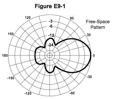
To evaluate the performance of directional antennas, manufacturers will measure the field strength at various points in a circle around the antenna and plot those field strengths, creating a chart called the azimuth antenna radiation pattern. Figure E9-1 is a typical azimuth antenna radiation pattern.

antenna radiation pattern
Figure E9-1. Typical antenna radiation pattern.

The antenna radiation pattern shows the relative strength of the signal generated by an antenna in its “far field.” The far-field of an antenna is the region where the shape of the antenna pattern is independent of distance.

QUESTION: What is the far field of an antenna? (E9B08)
ANSWER: The region where the shape of the antenna pattern is independent of distance

From the antenna radiation pattern, we can tell a bunch of things about the antenna. One of them is beamwidth. Beamwidth is a measure of the width of the main lobe of the radiation pattern. To determine the approximate beamwidth in a given plane of a directional antenna, find the two points where the signal strength of the antenna is 3 dB less than maximum and determine the angle between them. In the antenna radiation pattern shown in Figure E9-1, the 3-dB beamwidth is 50 degrees.

QUESTION: In the antenna radiation pattern shown in Figure E9-1, what is the beamwidth? (E9B01)
ANSWER: 50 degrees

Another parameter that’s important for a directional antenna is the front-to-back ratio. The front-to-back ratio is a measure of how directional an antenna is. The higher this ratio, the more directional the antenna. When the radiation pattern is set up so that the forward lobe has a value of 0, as it is in Figure E9-1, the front-to-back ratio is the maximum value of the rear lobe. In the antenna radiation pattern shown in Figure E9-1, the front-to-back ratio is 18 dB.

QUESTION: In the antenna radiation pattern shown in Figure E9-1, what is the front-to-back ratio? (E9B02)
ANSWER: 18 dB

A similar parameter is the front-to-side ratio. In the antenna radiation pattern shown in Figure E9-1, the front-to-side ratio is 14 dB.

QUESTION: In the antenna radiation pattern shown in Figure E9-1, what is the front-to-side ratio? (E9B03)
ANSWER: 14 dB

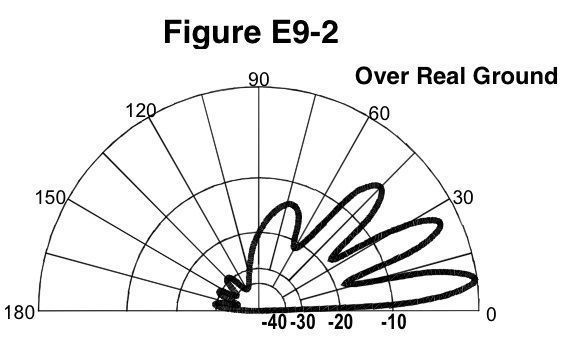
Because antennas radiate in three dimensions, the azimuth antenna pattern tells only part of the story. To get a complete picture of antenna performance, you also want to know what the antenna pattern is in the vertical direction. This type of pattern is called the elevation antenna pattern, and is shown in Figure E9-2. This elevation pattern shows four lobes in the forward direction, and the largest, or the lobe with the peak response, has an elevation angle of 7.5 degrees.

Figure E9-2: Elevation Pattern

QUESTION: What type of antenna pattern is shown in Figure E9-2? (E9B05)
ANSWER: Elevation

QUESTION: What is the elevation angle of peak response in the antenna radiation pattern shown in Figure E9-2? (E9B06)
ANSWER: 7.5 degrees

QUESTION: What is the front-to-back ratio of the radiation pattern shown in Figure E9-2? (E9B04)
ANSWER: 28 dB

Antenna design

To help design antennas, many amateurs use antenna modeling programs. Antenna modeling programs can provide the following information:

  • SWR vs. frequency charts
  • Polar plots of the far-field elevation and azimuth patterns
  • Antenna gain

The type of computer program technique commonly used for modeling antennas is method of moments. Programs that use the method of moments analysis technique model a wire as a series of segments, each having a uniform value of current.

QUESTION: What type of computer program technique is commonly used for modeling antennas? (E9B09)
ANSWER: Method of Moments

QUESTION: What is the principle of a Method of Moments analysis? (E9B10)
ANSWER: A wire is modeled as a series of segments, each having a uniform value of current

The more segments your simulation uses, the more accurate the results. The problem with using too many segments, though, is that the program will take a very long time to run. You don’t want to use too few segments, though. Decreasing the number of wire segments in an antenna model below the guideline of 10 segments per half-wavelength may cause the computed feed point impedance to be incorrect.

QUESTION: What is a disadvantage of decreasing the number of wire segments in an antenna model below 10 segments per half-wavelength? (E9B11)
ANSWER: The computed feed point impedance may be incorrect

Filed Under: 2020 Extra Class Study Guide, Antennas Tagged With: antenna modelling, radiation patterns

2020 Extra Class study guide: E9A Basic antenna parameters: radiation resistance, gain, beamwidth, efficiency, effective radiated power

March 2, 2020 By Dan KB6NU Leave a Comment

Antenna gain is one of the most misunderstood topics in amateur radio. There are several reasons for this, including:

  • Antennas don’t really have gain in the same way that an amplifier has gain. When you use a linear amplifier, you get more power out than you put in. Since transmitting antennas are passive devices, there’s no way to get more power out than you put in.
  • It’s not easy to measure antenna gain. There is no antenna gain meter that you can simply hook up to an antenna to measure its gain.

So, what is meant by antenna gain? Antenna gain is the ratio of the radiated signal strength of an antenna in the direction of maximum radiation to that of a reference antenna. What this means is that when you talk about antenna gain, you have to know what kind of antenna you’re comparing it to.

When talking about antenna gain, antenna engineers often refer to the “isotropic antenna.” In practice, an isotropic antenna is a theoretical antenna that has no gain in any direction. That is to say it radiates the power input to it equally in all directions.

QUESTION: What is an isotropic antenna? (E9A01)
ANSWER: A theoretical, omnidirectional antenna used as a reference for antenna gain

Let’s take a look at a practical example. The 1/2-wavelength dipole antenna is the most basic amateur radio antenna. The dipole actually has some gain over isotropic antenna. The reason for this is that it is directional. The signal strength transmitted broadside to the antenna will be greater than the signal strength transmitted off the ends of the antenna.

The gain of a 1/2-wavelength dipole in free space compared to an isotropic antenna is 2.15 dB. Sometimes, you’ll see this value as 2.15 dBi, where dBi denotes that an isotropic antenna is being used for this comparison. Since the isotropic antenna is a theoretical antenna, some think it’s better to compare an antenna to a dipole antenna. Let’s look at an example:

QUESTION: How much gain does an antenna have compared to a 1/2-wavelength dipole when it has 6 dB gain over an isotropic antenna? (E9A12)
ANSWER: 3.85 dB

You obtain this value by simply subtracting 2.15 dB from the 6 dB figure:

Gain over a dipole = gain over an isotropic antenna – 2.15 dB = 6 dBi – 2.15 dBi = 3.85 dBd

Sometimes, the gain over a dipole is denoted as dBd.

Effective radiated power

When you use an antenna that has gain, you are increasing the effectiveness of the power input to it in the direction the antenna is pointing. We call this the effective radiated power, but it is not just the transmitter’s output power times the gain of the antenna. You also have to take into account losses in other parts of the antenna system.

This is especially true for VHF and UHF repeater systems, where losses in the feedline, duplexer, and circulator can be significant. The power that reaches the antenna may be substantially lower than the power output of the transmitter.

Let’s look at an example. Say that your repeater station had a transmitter output power of 150 watts, a feed line loss of 2 dB, 2.2 dB duplexer loss, and 7 dBd antenna gain. To calculate the effective radiated power, you have to first subtract the losses from the gain, as expressed in dB to get the total gain of the system:

total system gain = 7 dB – 2 dB – 2.2 dB = 2.8 dB.

Now, recall that 3 dB corresponds to a power ration of 2:1, as shown in the table below. 2.8 dB would then be slight less than that. In fact, 2.8dB corresponds to a power ratio of approximately 1.905, so the effective radiated power is the transmitter output power times the total system gain:

effective radiated power = 150 W x 1.905 = 268 W.

QUESTION: What term describes station output, taking into account all gains and losses? (E9A13)
ANSWER: Effective radiated power

QUESTION: What is the effective radiated power relative to a dipole of a repeater station with 150 watts transmitter power output, 2 dB feed line loss, 2.2 dB duplexer loss, and 7 dBd antenna gain? (E9A02)
ANSWER: 286 watts

Let’s look at another example. In this example, your repeater station has 200 watts transmitter power output, 4 dB feed line loss, 3.2 dB duplexer loss, 0.8 dB circulator loss, and 10 dBd antenna gain. The total gain of the system is, therefore, 10 dB – 4 dB – 3.2 dB – 0.8 dB, or 2.0 dB. 2.0 dB corresponds to a power ratio of approximately 1.585, making the effective radiated power 200 W × 1.585 = 317 W. Note that in this system, the high feedline and duplexer losses almost completely negate the benefit of using a high gain antenna.

QUESTION: What is the effective radiated power relative to a dipole of a repeater station with 200 watts transmitter power output, 4 dB feed line loss, 3.2 dB duplexer loss, 0.8 dB circulator loss, and 10 dBd antenna gain? (E9A06)
ANSWER: 317 watts

Here’s a third example. Notice that in this example we comparing the effective radiated power to an isotropic antenna, not a dipole. In this example, the repeater station has 200 watts transmitter power output, 2 dB feed line loss, 2.8 dB duplexer loss, 1.2 dB circulator loss, and 7 dBi antenna gain. The total gain of the system is 7 dB – 2 dB – 2.8 dB – 1.2 dB, or 1.0 dB. 1.0 dB corresponds to a power ratio of approximately 1.26, and the effective radiated power equals 200 W × 1.26 = 252 W.

QUESTION: What is the effective isotropic radiated power of a repeater station with 200 watts transmitter power output, 2 dB feed line loss, 2.8 dB duplexer loss, 1.2 dB circulator loss, and 7 dBi antenna gain? (E9A07)
ANSWER: 252 watts

Feedpoint impedance

Other antenna parameters are also important, of course. One of the most basic antenna parameters is the feedpoint impedance. The reason that the feedpoint impedance is important is that you want the feedpoint impedance to match the impedance of the feedline that you use and the output impedance of the transmitter. When these are all equal, we say that the system is “matched,” and it will radiate the maximum amount of energy.

Many factors may affect the feed point impedance of an antenna, including antenna height, conductor length/diameter ratio and location of nearby conductive objects. For example, we say that the feedpoint impedance of a half-wavelength, dipole antenna is 72 Ω, but that’s only really true if the antenna is in free space. When it’s closer to the ground than a quarter wavelength, then the impedance will be different. That’s why you have to tune the antenna when you install it.

QUESTION: Which of the following factors affect the feed point impedance of an antenna? (E9A04)
ANSWER: Antenna height

Radiation resistance

Another antenna parameter that’s frequently bandied about is radiation resistance. The radiation resistance of an antenna is the value of a resistance that would dissipate the same amount of power as that radiated from an antenna. In the case of an antenna, however, that power isn’t being turned into heat, but rather turned into radio waves. The total resistance of an antenna system is the sum of the radiation resistance and ohmic resistance. The ohmic resistance is the combination of all the physical resistances in the system, including the resistance of the antenna wire, feed line, and connections.

QUESTION: What is the radiation resistance of an antenna? (E9A03)
ANSWER: The value of a resistance that would dissipate the same amount of power as that radiated from an antenna

QUESTION: What is included in the total resistance of an antenna system? (E9A05)
ANSWER: Radiation resistance plus loss resistance

If you know the radiation resistance and the ohmic resistance of an antenna, you can calculate its efficiency. Antenna efficiency equals the radiation resistance divided by the total resistance.

QUESTION: What is antenna efficiency? (E9A09)
ANSWER: Radiation resistance divided by total resistance

Vertical antennas, bandwidth

Vertical antennas are sometimes criticized as being inefficient antennas. The main reason for this is the lack of a good radial system. Installing a good radial system will improve a quarter-wave vertical’s efficiency. Another for poor vertical performance is poor soil conductivity. If soil conductivity is poor, ohmic resistance will be high, and the antenna’s efficiency will be low.

QUESTION: Which of the following improves the efficiency of a ground-mounted quarter-wave vertical antenna? (E9A10)
ANSWER: Installing a radial system

QUESTION: Which of the following factors determines ground losses for a ground-mounted vertical antenna operating in the 3 MHz to 30 MHz range? (E9A11)
ANSWER: Soil conductivity

Antenna bandwidth is the frequency range over which an antenna satisfies a performance requirement. Normally, the performance requirement is an SWR of 2:1 or less. In fact, you’ll sometimes hear this parameter referred to as the 2:1 SWR bandwidth.

QUESTION: What is antenna bandwidth? (E9A08)
ANSWER: The frequency range over which an antenna satisfies a performance requirement

Filed Under: 2020 Extra Class Study Guide

2020 Extra Class study guide: E7H – Oscillators and signal sources: types of oscillators; synthesizers and phase-locked loops; direct digital synthesizers; stabilizing thermal drift; microphonics; high-accuracy oscillators

February 28, 2020 By Dan KB6NU Leave a Comment

Oscillator circuits are one of the basic building blocks of amateur radio equipment. Oscillator circuits are not only used to generate the signals we transmit, they are also an integral part of receivers, such as the superheterodyne receiver.

You can think of an oscillator as an amplifier with a tuned circuit that provides positive feedback. This tuned circuit might be an LC circuit or a crystal. The values of the components in the tuned circuit determine the output frequency of the oscillator. There are three types of oscillator circuits commonly used in Amateur Radio equipment: Colpitts, Hartley and Pierce. Colpitts and Hartley oscillator circuits are commonly used in VFOs.

QUESTION: What are three oscillator circuits used in amateur radio equipment? (E7H01)
ANSWER: Colpitts, Hartley and Pierce
QUESTION: Which of the following oscillator circuits are commonly used in VFOs? (E7H06)
ANSWER: Colpitts and Hartley

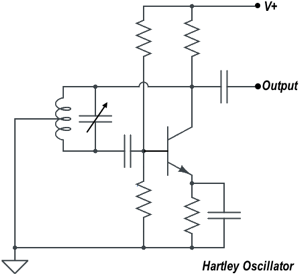
In a Hartley oscillator (shown in the figure below), positive feedback is supplied through a tapped coil.


QUESTION: How is positive feedback supplied in a Hartley oscillator? (E7H03)
ANSWER: Through a tapped coil

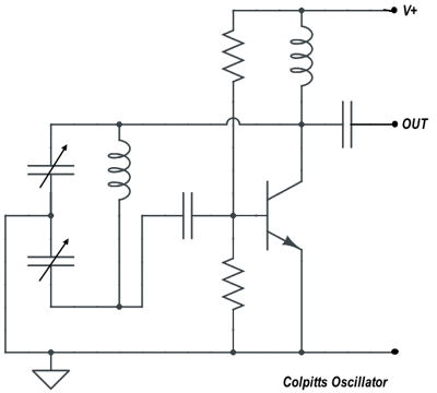
In a Colpitts oscillator (shown below), positive feedback is supplied through a capacitive divider.

Colpitts Oscillator


QUESTION: How is positive feedback supplied in a Colpitts oscillator? (E7H04)
ANSWER: Through a capacitive divider

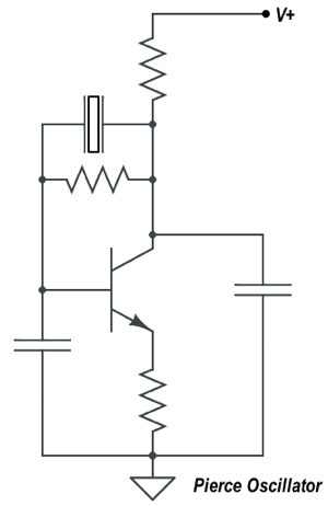
In a Pierce oscillator (shown below), positive feedback is supplied through a quartz crystal. To ensure that a crystal oscillator provides the frequency specified by the crystal manufacturer, you must provide the crystal with a specified parallel capacitance.


Pierce Oscillator


QUESTION: How is positive feedback supplied in a Pierce oscillator? (E7H05)
ANSWER: Through a quartz crystal

QUESTION: Which of the following must be done to ensure that a crystal oscillator provides the frequency specified by the crystal manufacturer? (E7H12)
ANSWER: Provide the crystal with a specified parallel capacitance

One problem that can occur with oscillators that use LC circuits is that their output frequency drifts because as the capacitors heat up their values change and the resonant frequency of the LC circuit changes. This phenomenon is called thermal drift. To prevent this from happening, use NPO capacitors. The capacitance of NPO capacitors changes very little over normal operating temperatures.

QUESTION: Which of the following components can be used to reduce thermal drift in crystal oscillators? (E7H08)
ANSWER: NP0 capacitors

Another problem that oscillators sometimes have is called microphonics. We say that an oscillator has a microphonic problem if the oscillator frequency changes due to mechanical vibration. An oscillator’s microphonic responses can be reduced by mechanically isolating the oscillator from its enclosure.

QUESTION: What is a microphonic? (E7H02)
ANSWER: Changes in oscillator frequency due to mechanical vibration

QUESTION: How can an oscillator’s microphonic responses be reduced? (EH707)
ANSWER: Mechanically isolate the oscillator circuitry from its enclosure

Digital frequency synthesizers

Most modern amateur radio transceivers use digital frequency synthesizers instead of analog oscillators to generate RF signals. One reason for this is that they are much more stable than analog oscillators. The two main types of digital frequency synthesizers are the direct digital synthesizer and the phase-locked loop synthesizer.

A direct digital synthesizer is the type of frequency synthesizer circuit that uses a phase accumulator, lookup table, digital to analog converter and a low-pass anti-alias filter. The information contained in the lookup table of a direct digital frequency synthesizer are the amplitude values that represent a sine-wave output.

QUESTION: What type of frequency synthesizer circuit uses a phase accumulator, lookup table, digital to analog converter, and a low-pass anti-alias filter? (E7H09)
ANSWER: A direct digital synthesizer

QUESTION: What information is contained in the lookup table of a direct digital synthesizer (DDS)? (E7H10)
ANSWER: Amplitude values that represent the desired waveform

Frequency synthesizers that use phase-locked loops are also popular. A phase-locked loop is an electronic servo loop consisting of a phase detector, a low-pass filter, a voltage-controlled oscillator, and a stable reference oscillator. Frequency synthesis, FM demodulation are two functions that can be performed by a phase-locked loop.

QUESTION: What is a phase-locked loop circuit? (E7H14)
ANSWER: An electronic servo loop consisting of a phase detector, a low-pass filter, a voltage-controlled oscillator, and a stable reference oscillator

QUESTION: Which of these functions can be performed by a phase-locked loop? (E7H15)
ANSWER: Frequency synthesis, FM demodulation

Both direct digital synthesizers and phase-locked loop synthesizers have issues with spectral purity. The major spectral impurity components of direct digital synthesizers are spurious signals at discrete frequencies.

QUESTION: What are the major spectral impurity components of direct digital synthesizers? (E7H11)
ANSWER: Spurious signals at discrete frequencies

Because frequency multipliers are often used for generating RF signals at microwave frequencies, it is very important that the oscillators used in microwave transmitters are highly accurate and stable. Any inaccuracy or instability will be multiplied along with the desired frequency. To achieve high accurate and stability, oscillators used for microwave transmission and reception, can use a GPS signal reference, a rubidium stabilized reference oscillator, or a temperature-controlled high Q dielectric resonator.

QUESTION: Which of the following is a technique for providing highly accurate and stable oscillators needed for microwave transmission and reception? (E7H13)
ANSWER: All these choices are correct

  • Use a GPS signal reference
  • Use a rubidium stabilized reference oscillator
  • Use a temperature-controlled high Q dielectric resonator

Filed Under: 2020 Extra Class Study Guide Tagged With: direct digital synthesizers, oscillators

2020 Extra Class study guide: E7G – Active filters and op-amps: active audio filters; characteristics; basic circuit design; operational amplifiers

February 26, 2020 By Dan KB6NU Leave a Comment

Operational amplifiers, or op-amps for short, are integrated circuits that include a high-gain, direct-coupled differential amplifier with very high input and very low output impedance. They can be used to build amplifiers, filter circuits, and many other types of circuits that do analog signal processing.

QUESTION: What is an operational amplifier? (E7G12)
ANSWER: A high-gain, direct-coupled differential amplifier with very high input impedance and very low output impedance

QUESTION: What is the typical input impedance of an op-amp? (E7G03)
ANSWER: Very high

QUESTION: What is the typical output impedance of an op-amp? (E7G01)
ANSWER: Very low

While the gain of an ideal operational amplifier does not vary with frequency, op amps in the real world do have a finite bandwidth. Some modern op amps can be used at high frequencies, but many of the older ones can’t be used at frequencies above a couple of MHz. To find out if you can use an op amp at the frequency of your signals, check out the gain-bandwidth specification. The gain-bandwidth specification is the frequency at which the open-loop gain of the amplifier equals one.

QUESTION: How does the gain of an ideal operational amplifier vary with frequency? (E7G08)
ANSWER: It does not vary with frequency

QUESTION: What is the gain-bandwidth of an operational amplifier? (E7G06)
ANSWER: The frequency at which the open-loop gain of the amplifier equals one

Ideally, with no input signal, there should be no voltage difference between the two input terminals, and the output voltage should also be zero. Since no electronic component is ideal, there will be a voltage between these two terminals. We call this the input offset voltage. Put another way, the op-amp input-offset voltage is the differential input voltage needed to bring the open-loop output voltage to zero.

QUESTION: What is meant by the “op-amp input offset voltage”? (E7G04)
ANSWER: The differential input voltage needed to bring the open loop output voltage to zero

Because they are active components—that is to say that they amplify—filters made with op amps are called active filters. One use for an op-amp active filter is as an audio filter in a receiver. The values of capacitors and resistors external to the op-amp primarily determine the gain and frequency characteristics of an op-amp RC active filter.

Ringing is one undesirable characteristic of an op-amp filter. One effect of ringing in a filter is that it adds undesired oscillations to the desired signal. One way to prevent unwanted ringing and audio instability in a multi-section op-amp RC audio filter circuit is to restrict both gain and Q.

QUESTION: What is ringing in a filter? (E7G02)
ANSWER: Undesired oscillations added to the desired signal
QUESTION: How can unwanted ringing and audio instability be prevented in an op-amp RC audio filter circuit? (E7G05)
ANSWER: Restrict both gain and Q

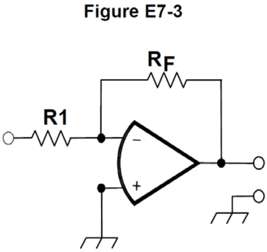
Calculating the gain and output voltage of an op amp circuit is relatively straightforward. The gain is simply RF/Rin. In the op amp circuit shown in Figure E7-3, Rin = R1. The output voltage of a circuit is then the input voltage times the gain.

QUESTION: What magnitude of voltage gain can be expected from the circuit in Figure E7-3 when R1 is 10 ohms and RF is 470 ohms? (E7G07)
ANSWER: 47
If R1 is 10 ohms and RF is 470 ohms, the gain is 470/10, or 47.

QUESTION: What absolute voltage gain can be expected from the circuit in Figure E7-3 when R1 is 1800 ohms and RF is 68 kilohms? (E7G10)
ANSWER: 38
If R1 is 1800 ohms and RF is 68 kilohms, the gain is 68,000/1,800, or about 38.

QUESTION: What absolute voltage gain can be expected from the circuit in Figure E7-3 when R1 is 3300 ohms and RF is 47 kilohms? (E7G11)
ANSWER: 14
If R1 is 3300 ohms and RF is 47 kilohms, the gain is 47,000/3,300, or about 14.

QUESTION: What will be the output voltage of the circuit shown in Figure E7-3 if R1 is 1000 ohms, RF is 10,000 ohms, and 0.23 volts DC is applied to the input? (E7G09)
ANSWER: –2.3 volts
If R1 is 1000 ohms, RF is 10,000 ohms, the gain of the circuit will be 10,000/1,000 or 10, and the output voltage will be equal to the input voltage times the gain. 0.23 V × 10 = 2.3 V, but since the input voltage is being applied to the negative input, the output voltage will be negative.

Filed Under: 2020 Extra Class Study Guide Tagged With: filters, op amps

2020 Extra Class study guide: E7F – DSP filtering and other operations; software defined radio fundamentals; DSP modulation and demodulation

February 25, 2020 By Dan KB6NU Leave a Comment

Some modern radios modulate and demodulate signals entirely in software. This type of radio is called a software-defined radio, or SDR. One type of SDR uses a process called direct digital conversion to convert the analog radio signal into a series of numbers. What this type of SDR does is digitize an incoming RF signal with an analog-to-digital converter without being mixed with a local oscillator signal.

QUESTION: What is meant by direct digital conversion as applied to software defined radios? (E7F01)
ANSWER: Incoming RF is digitized by an analog-to-digital converter without being mixed with a local oscillator signal

Analog-to-digital converter specifications are crucial for a software-defined radio. Sample rate is one such specification. The sample rate determines the maximum receive bandwidth of a direct digital conversion SDR. An analog signal must be sampled at twice the rate of the highest frequency component of the signal by an analog-to-digital converter so that the signal can be accurately reproduced.

QUESTION: What aspect of receiver analog-to-digital conversion determines the maximum receive bandwidth of a Direct Digital Conversion SDR? (E7F10)
ANSWER: Sample rate

QUESTION: How frequently must an analog signal be sampled by an analog-to-digital converter so that the signal can be accurately reproduced? (E7F05)
ANSWER: At least twice the rate of the highest frequency component of the signal

Voltage resolution is also important. In the absence of atmospheric or thermal noise, the reference voltage level and sample width in bits sets the minimum detectable signal level for an SDR. The reference voltage is basically the maximum detectable voltage, while the number of bits determines the resolution of the analog-to-digital converter. For example, if an analog-to-digital converter had a reference voltage of 1 V, the minimum number of bits required to sample a signal at a resolution of 1 millivolt is 10 bits. The reason for this is that 210 = 1,024, meaning that each bit represents approximately 1 mV.

QUESTION: What sets the minimum detectable signal level for a direct-sampling SDR receiver in the absence of atmospheric or thermal noise? (E7F11)
ANSWER: Reference voltage level and sample width in bits

QUESTION: What is the minimum number of bits required for an analog-to-digital converter to sample a signal with a range of 1 volt at a resolution of 1 millivolt? (E7F06)
ANSWER: 10 bits

Modern software defined radios convert an incoming signal into two data streams: I and Q. The I and Q data streams are 90 degrees out of phase with one another, and as a result, the two data streams not only show how the amplitude of a signal is changing, but how the phase of a signal is changing. Perhaps the most common operation that is performed on the I and Q signals is a Fast Fourier Transform (FFT). The Fast Fourier Transform converts digital signals from the time domain to the frequency domain.

QUESTION: What function is performed by a Fast Fourier Transform? (E7F07)
ANSWER: Converting digital signals from the time domain to the frequency domain

Once a signal has been digitized, or converted into a series of numbers, it can be digitally filtered. We call this digital signal processing, or DSP For example, to remove unwanted noise from a received SSB signal you would use a DSP audio filter called an adaptive filter. Another type of digital filter used in SDRS is the finite impulse, or FIR, filter. An advantage of a Finite Impulse Response (FIR) filter vs an Infinite Impulse Response (IIR) digital filter is that FIR filters delay all frequency components of the signal by the same amount.

QUESTION: What kind of digital signal processing audio filter is used to remove unwanted noise from a received SSB signal? (E7F02)
ANSWER: An adaptive filter

QUESTION: Which of the following is an advantage of a Finite Impulse Response (FIR) filter vs an Infinite Impulse Response (IIR) digital filter? (E7F15)
ANSWER: FIR filters can delay all frequency components of the signal by the same amount

Taps in a digital signal processing filter provide incremental signal delays for filter algorithms. More taps would allow a digital signal processing filter to create a sharper filter response.

QUESTION: What is the function of taps in a digital signal processing filter? (E7F13)
ANSWER: Provide incremental signal delays for filter algorithms

QUESTION: Which of the following would allow a digital signal processing filter to create a sharper filter response? (E7F14)
ANSWER: More taps

Because so many calculations are required to do digital signal processing, SDRs sometimes use a technique called decimation, which allows them to use less-powerful processors. Decimation reduces the effective sample rate by removing samples when using a digital filter. They can get away with this because the signal of interest will usually have a significantly lower bandwidth than the digitized signal. An anti-aliasing digital filter must be used with a digital decimator because it peaks the response of the decimator, improving bandwidth.

QUESTION: What is the function of decimation? (E7F08)
ANSWER: Reducing the effective sample rate by removing samples

QUESTION: Why is an anti-aliasing digital filter required in a digital decimator? (E7F09)
ANSWER: It removes high-frequency signal components that would otherwise be reproduced as lower frequency components

Signals can also be generated using SDR techniques. For example, a common method of generating an SSB signal using digital signal processing is to combine signals with a quadrature phase relationship. The type of digital signal processing filter used to generate an SSB signal is a Hilbert-transform filter.

QUESTION: What is a common method of generating an SSB signal using digital signal processing? (E7F04)
ANSWER: Signals are combined in quadrature phase relationship

QUESTION: What type of digital signal processing filter is used to generate an SSB signal? (E7F03)
ANSWER: A Hilbert-transform filter

Filed Under: 2020 Extra Class Study Guide

2020 Extra Class study guide: E7E – Modulation and demodulation: reactance, phase and balanced modulators; detectors; mixer stages

February 24, 2020 By Dan KB6NU Leave a Comment

Modulation is the process of adding information, such as voice or digital information, to a carrier signal. The most common types of modulation that we use in amateur radio are amplitude modulation (AM) and frequency modulation (FM). Single-sideband, or SSB, is a form of amplitude modulation.

To frequency modulate a carrier, a transmitter will sometimes use a modulator that varies the phase of the signal. This process is called phase modulation (PM), and the type of modulator used to phase modulate a signal is called a reactance modulator. It uses an electrically variable inductance or capacitance to produce PM or FM signals.

QUESTION: Which of the following can be used to generate FM phone emissions? (E7E01)
ANSWER: A reactance modulator on the oscillator

QUESTION: What is the function of a reactance modulator? (E7E02)
ANSWER: To produce PM or FM signals by using an electrically variable inductance or capacitance

When generating FM signals, a pre-emphasis network is often added to an FM transmitter to boost the higher audio frequencies. Conversely, de-emphasis is commonly used in FM communications receivers to maintain compatibility with transmitters using phase modulation.

QUESTION: What circuit is added to an FM transmitter to boost the higher audio frequencies? (E7E05)
ANSWER: A pre-emphasis network

QUESTION: Why is de-emphasis commonly used in FM communications receivers? (E7E06)
ANSWER: For compatibility with transmitters using phase modulation


Amplitude modulation and single-sideband signals are produced using mixer circuits. The carrier frequency and the baseband signals are input to the mixer circuit which produces an amplitude modulated output. In other words, the term baseband refers to the frequency range of a modulating signal prior to it being mixed with a carrier signal. A mixer combines the carrier and baseband signals and produces four different output frequencies: the two input frequencies along and the sum and difference of the two input frequencies. When using a mixer, you must take care not to use too high of a signal level at the mixer inputs, or it may generate spurious products.

QUESTION: What is meant by the term “baseband” in radio communications? (E7E07)
ANSWER: The frequency range occupied by a message signal prior to modulation

QUESTION: What are the principal frequencies that appear at the output of a mixer circuit? (E7E08)
ANSWER: The two input frequencies along with their sum and difference frequencies

QUESTION: What occurs when an excessive amount of signal energy reaches a mixer circuit? (E7E09)
ANSWER: Spurious mixer products are generated

Single sideband is most often used for phone transmission on the HF bands and for weak-signal operation on the VHF and UHF bands. One way a single-sideband phone signal can be generated is by using a balanced modulator followed by a filter. A balanced modulator is a type of mixer, but its output contains only the two sidebands, not the carrier or baseband signal. A filter follows the balanced modulator to eliminate the undesired sideband.

QUESTION: What is one way a single-sideband phone signal can be generated? (E7E04)
ANSWER: By using a balanced modulator followed by a filter

At the receiving station, a modulated signal has to be demodulated. Amplitude modulated signals are often demodulated using a simple diode detector circuit. A diode detector rectifies and filters a modulated signal, thereby producing an audio signal at its output. For demodulating SSB signals, you want something a little more sophisticated, like a product detector. A product detector is actually a frequency mixer, followed by a filter . Its output is the product of the modulated signal and a beat frequency oscillator, hence the name.

QUESTION: How does a diode envelope detector function? (E7E10)
ANSWER: By rectification and filtering of RF signals

QUESTION: Which type of detector circuit is used for demodulating SSB signals? (E7E11)
ANSWER: Product detector

FM receivers use a circuit called a discriminator to detect an FM signal. A discriminator converts a signal that changes in frequency to one that changes in amplitude.

QUESTION: What is a frequency discriminator stage in a FM receiver? (E7E03)
ANSWER: A circuit for detecting FM signals

Filed Under: 2020 Extra Class Study Guide

2020 Extra Class study guide: E7D – Power supplies and voltage regulators; Solar array charge controllers

February 20, 2020 By Dan KB6NU Leave a Comment

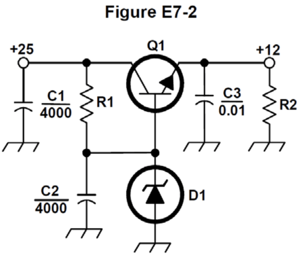
Linear power supplies are a type of power supply used in amateur radio stations. They are called linear power supplies because they use ICs called linear electronic voltage regulator to maintain a constant output voltage. The way they regulate the output voltage is to vary the conduction of current through a control element, usually a transistor. The circuit shown in Figure E7-2 below is a linear voltage regulator, and the control element is Q1. Q1, often called the pass transistor, controls the current supplied to the load, thereby keeping the output voltage constant even when the load varies. C2 bypasses rectifier output ripple around D1.

QUESTION: What type of circuit is shown in Figure E7-2? (E7D08)
ANSWER: Linear voltage regulator

QUESTION: How does a linear electronic voltage regulator work? (E7D01)
ANSWER: The conduction of a control element is varied to maintain a constant output voltage

QUESTION: What is the purpose of Q1 in the circuit shown in Figure E7-2? (E7D06)
ANSWER: It controls the current supplied to the load

QUESTION: What is the function of the pass transistor in a linear voltage regulator circuit? (E7D11)
ANSWER: Maintains nearly constant output voltage over a wide range of load current

QUESTION: What is the purpose of C2 in the circuit shown in Figure E7-2? (E7D07)
ANSWER: It bypasses rectifier output ripple around D1

Power supply designers typically use Zener diode as the voltage reference in a linear voltage regulator. D1 in Figure E7-2 is a zener diode.

QUESTION: What device is typically used as a stable voltage reference in a linear voltage regulator? (E7D03)
ANSWER: A Zener diode

There are two kinds of linear voltage regulators—the series regulator and the shunt regulator. A series regulator is the type of linear voltage regulator that usually makes the most efficient use of the primary power source. A shunt regulator is the type of linear voltage regulator that places a constant load on the unregulated voltage source.

QUESTION: Which of the following types of linear voltage regulator usually make the most efficient use of the primary power source? (E7D04)
ANSWER: A series regulator

QUESTION: Which of the following types of linear voltage regulator places a constant load on the unregulated voltage source? (E7D05)
ANSWER: A shunt regulator

An important analog voltage regulator specification is the drop-out voltage, which is the minimum input-to-output voltage required to maintain regulation. For example, if an analog voltage regulator has a drop-out voltage of 2 V, the input voltage must be at least 11 V in order to maintain an output voltage of 9 V.

QUESTION: What is the dropout voltage of an analog voltage regulator? (E7D12)
ANSWER: Minimum input-to-output voltage required to maintain regulation

Power dissipation is also important when designing a power supply with a series-connected linear voltage regulator. Excessive power dissipation reduces the efficiency of the supply and could require that you use large heat sinks to dissipate the power. The power dissipation by a series connected linear voltage regulator is the voltage difference from input to output multiplied by output current.

QUESTION: What is the equation for calculating power dissipated by a series linear voltage regulator? (E7D13)
ANSWER: Voltage difference from input to output multiplied by output current

Switching power supplies

Nowadays, you are as likely to find a switching power supply in an amateur radio station as you are a linear power supply. Switching power supplies use a much different method of regulating the output voltage than a linear supply. Instead of controlling the current through a control element, a switching supply varies the duty cycle of the control element to produce a constant average output voltage.

QUESTION: What is a characteristic of a switching electronic voltage regulator? (E7D02)
ANSWER: The controlled device’s duty cycle is changed to produce a constant average output voltage

Switching power supplies are usually less expensive and lighter than a linear power supply with the same output rating. Switching supplies are also generally more efficient than linear power supplies. The main reason that a high-frequency switching type high voltage power supply can be less expensive, lighter in weight, and more efficient than a linear power supply is that the high frequency inverter design uses much smaller transformers and filter components for an equivalent power output. Butt, this comes at a cost. Switching supply circuits are more complicated than the circuitry in a linear supply and may generate RF noise.

QUESTION: What is the primary reason that a high-frequency switching type high-voltage power supply can be both less expensive and lighter in weight than a conventional power supply? (E7D10)
ANSWER: The high frequency inverter design uses much smaller transformers and filter components for an equivalent power output

High-voltage power supplies

Most HF transceivers and VHF/UHF transceivers operate at a relatively low voltage. This is normally around 12 – 15 VDC. Some devices, such as older tube equipment and linear amplifiers need higher voltages to operate. These power supplies are quite different than the low-voltage linear and switching supplies describe above.

High-voltage supplies may also have a step-start circuit. The purpose of a “step-start” circuit in a high-voltage power supply is to allow the filter capacitors to charge gradually, thereby reducing the amount of current the supply draws when turned on.

QUESTION: What is the purpose of a step-start circuit in a high-voltage power supply? (E7D15)
ANSWER: To allow the filter capacitors to charge gradually

When several electrolytic filter capacitors are connected in series to increase the operating voltage of a power supply filter circuit, resistors should be connected across each capacitor. Doing this helps to equalize the voltage drop across each capacitor, discharge the capacitors when the supply is turned off, and provide a minimum load on the supply.

QUESTION: What is the purpose of connecting equal-value resistors across power supply filter capacitors connected in series? (E7D14)
ANSWER: All these choices are correct

    • Equalize the voltage across each capacitor
    • Discharge the capacitors when voltage is removed
    • Provide a minimum load on the supply

Solar array charge controllers

Solar array charge controllers are voltage or current regulators that are used when charging batteries from a solar array. The main reason to use a charge controller with a solar power system is to prevent battery damage by overcharging them. Most solar panels that are rated at 12 V actually output 16 to 20 V, and if that output is not regulated, batteries connected to the solar panel may be damaged from overcharging.

QUESTION: What is the main reason to use a charge controller with a solar power system? (E7D09)
ANSWER: Prevention of battery damage due to overcharge

Filed Under: 2020 Extra Class Study Guide Tagged With: power supplies

  • « Go to Previous Page
  • Page 1
  • Page 2
  • Page 3
  • Page 4
  • Page 5
  • Go to Next Page »

Primary Sidebar

No Nonsense Technician Class License Study Guide (for tests given between July 2026 and June 2030)

New No Nonsense Technican Class Study Guide now available!

The 2026 version of my Tech Class study guide is now available, and as always, the PDF version is FREE!. The ePub version costs $11.97, and a Kindle version and paperback version will be available on Amazon shortly.

Click here to get all of my "No Nonsense" study guides.

Also available: The CW Geek's Guide to Having Fun with Morse Code

W5SWL.Com
Retevis Ailunce H1 DMR Radio
DXpander: Cobweb antennas, Laser Cutting

You’ve got mail!

Enter your email address below and get an email every time I publish a new post.

Email


I frequently teach classes to help newcomers get their licenses. The next class will take place on Saturday, February 7, 2026 on the University of Michigan campus. Click here for more information.

If you can't make the class, subscribe to the mailing list to be notified of when the next class will be held.

You can always download my free study guide, and if you have any questions about the classes, or amateur radio in general, please feel free to email me directly.

Support KB6NU.Com

Donate $7.30 and get two of these cool stickers. Measuring 4.25-in. W by 2.75-in. H, it's perfect for your car, your shack, or wherever!

Contact me

If you have a question or comment about one of my blog posts, or a question about any of the material in my study guides, or just a question about ham radio in general, you can email me at [email protected].

Blogs You Should Also Read

  • AE5X: A CW-centric blog from Kingswood, Texas
  • K0LWC Blog
  • LA3ZA Ham Radio Blog
  • Little Radios, Big Fun – WB3GCK
  • Mr. Vacuum Tube's Blog
  • Radio Artisan – K3NG
  • The K0NR Weblog
  • VE3WDM's QRP Ham Radio Blog
  • W2LJ’s Blog

Ham Radio Websites

  • Dashtoons – The Hammin' Comedy by Jeff K1NSS

Podcasts

  • ICQ Podcast
  • Linux in the Ham Schack
  • No Nonsense Amateur Radio Podcast
  • Resonant Frequency Amateur Radio Podcast

Recent Comments

  • Dan KB6NU on Finally, a Loop for 10m.
  • Dan KB6NU on 1930s cards for my collection of QSLs from stations whose callsigns spell words
  • Sean on Finally, a Loop for 10m.
  • Bill Waslo on 1930s cards for my collection of QSLs from stations whose callsigns spell words
  • C M Wetzel KD8TNF on The Wesco BN-1

Meta

  • Log in
  • Entries feed
  • Comments feed
  • WordPress.org

Footer

Copyright © 2026 Daniel M. Romanchik, KB6NU · Log in