• Skip to primary navigation
  • Skip to main content
  • Skip to primary sidebar
  • Skip to footer

KB6NU's Ham Radio Blog

KB6NU's Ham Radio Blog
  • HOME
  • Study Guides
  • Teach a One-Day Tech Class
  • W8SRC Repeater Guide
  • Advertise
  • Hire Me

op amps

Trade magazine articles: Op amps, microcontroller measures frequency and period, antenna basics

January 22, 2022 By Dan KB6NU Leave a Comment

All three articles in this post are from Electronic Design….Dan

Op Amps for Linear Designs: Back to the Basics

Op amps are the basic building blocks for much of linear circuit design. You probably learned about them in college and even designed some products containing an op amp.  As an electronic engineer, you will at some point in your career probably need to design a linear circuit.
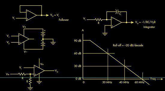
If you’re not an advanced linear or analog circuit designer, perhaps the best way to fulfill your linear design needs is to use an op amp. These ICs are widely available, inexpensive, and can be configured in hundreds if not thousands of ways to satisfy most linear requirements. Here’s a summary and update on these versatile devices…..more


Microcontroller Efficiently Measures Frequency and Period

When you need to take accurate timing measurements in hardware without overloading a microcontroller, the signal measurement timer module (SMT) in the Microchip16F1619 PIC microcontrolleris perfectly suitable for this application. The SMT module captures features of a signal such as Period and Frequency, among others. This design measures input frequency signals within the range of 8 Hz to 10 MHz, and Period signals within the range of 0.1 µs to 125 ms…..more


Welcome To Antennas 101

Antennas are much more than simple devices connected to every radio. They’re the transducers that convert the voltage from a transmitter into a radio signal. And they pick radio signals out of the air and convert them into a voltage for recovery in a receiver.

Typically taken for granted and left for the last minute in a design, antennas are nonetheless critical for establishing and maintaining a reliable radio connection. They may look complex and enigmatic to most engineers, especially EEs working with wireless applications for the first time—not to mention that they come in a seemingly infinite variety of sizes and shapes. However, a brief review of the essentials can help allay any design worries….more
Filed Under: Antennas, Building/Homebrew, Electronic Components, Electronics Theory, Microcontrollers Tagged With: op amps, PIC

2020 Extra Class study guide: E7G – Active filters and op-amps: active audio filters; characteristics; basic circuit design; operational amplifiers

February 26, 2020 By Dan KB6NU Leave a Comment

Operational amplifiers, or op-amps for short, are integrated circuits that include a high-gain, direct-coupled differential amplifier with very high input and very low output impedance. They can be used to build amplifiers, filter circuits, and many other types of circuits that do analog signal processing.

QUESTION: What is an operational amplifier? (E7G12)
ANSWER: A high-gain, direct-coupled differential amplifier with very high input impedance and very low output impedance

QUESTION: What is the typical input impedance of an op-amp? (E7G03)
ANSWER: Very high

QUESTION: What is the typical output impedance of an op-amp? (E7G01)
ANSWER: Very low

While the gain of an ideal operational amplifier does not vary with frequency, op amps in the real world do have a finite bandwidth. Some modern op amps can be used at high frequencies, but many of the older ones can’t be used at frequencies above a couple of MHz. To find out if you can use an op amp at the frequency of your signals, check out the gain-bandwidth specification. The gain-bandwidth specification is the frequency at which the open-loop gain of the amplifier equals one.

QUESTION: How does the gain of an ideal operational amplifier vary with frequency? (E7G08)
ANSWER: It does not vary with frequency

QUESTION: What is the gain-bandwidth of an operational amplifier? (E7G06)
ANSWER: The frequency at which the open-loop gain of the amplifier equals one

Ideally, with no input signal, there should be no voltage difference between the two input terminals, and the output voltage should also be zero. Since no electronic component is ideal, there will be a voltage between these two terminals. We call this the input offset voltage. Put another way, the op-amp input-offset voltage is the differential input voltage needed to bring the open-loop output voltage to zero.

QUESTION: What is meant by the “op-amp input offset voltage”? (E7G04)
ANSWER: The differential input voltage needed to bring the open loop output voltage to zero

Because they are active components—that is to say that they amplify—filters made with op amps are called active filters. One use for an op-amp active filter is as an audio filter in a receiver. The values of capacitors and resistors external to the op-amp primarily determine the gain and frequency characteristics of an op-amp RC active filter.

Ringing is one undesirable characteristic of an op-amp filter. One effect of ringing in a filter is that it adds undesired oscillations to the desired signal. One way to prevent unwanted ringing and audio instability in a multi-section op-amp RC audio filter circuit is to restrict both gain and Q.

QUESTION: What is ringing in a filter? (E7G02)
ANSWER: Undesired oscillations added to the desired signal
QUESTION: How can unwanted ringing and audio instability be prevented in an op-amp RC audio filter circuit? (E7G05)
ANSWER: Restrict both gain and Q

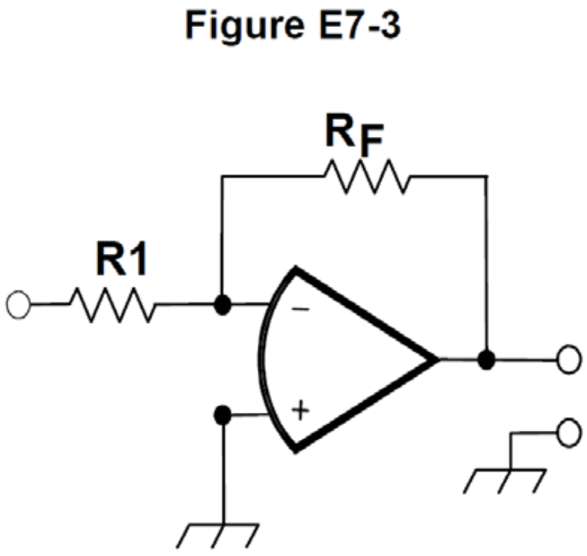
Calculating the gain and output voltage of an op amp circuit is relatively straightforward. The gain is simply RF/Rin. In the op amp circuit shown in Figure E7-3, Rin = R1. The output voltage of a circuit is then the input voltage times the gain.

QUESTION: What magnitude of voltage gain can be expected from the circuit in Figure E7-3 when R1 is 10 ohms and RF is 470 ohms? (E7G07)
ANSWER: 47
If R1 is 10 ohms and RF is 470 ohms, the gain is 470/10, or 47.

QUESTION: What absolute voltage gain can be expected from the circuit in Figure E7-3 when R1 is 1800 ohms and RF is 68 kilohms? (E7G10)
ANSWER: 38
If R1 is 1800 ohms and RF is 68 kilohms, the gain is 68,000/1,800, or about 38.

QUESTION: What absolute voltage gain can be expected from the circuit in Figure E7-3 when R1 is 3300 ohms and RF is 47 kilohms? (E7G11)
ANSWER: 14
If R1 is 3300 ohms and RF is 47 kilohms, the gain is 47,000/3,300, or about 14.

QUESTION: What will be the output voltage of the circuit shown in Figure E7-3 if R1 is 1000 ohms, RF is 10,000 ohms, and 0.23 volts DC is applied to the input? (E7G09)
ANSWER: –2.3 volts
If R1 is 1000 ohms, RF is 10,000 ohms, the gain of the circuit will be 10,000/1,000 or 10, and the output voltage will be equal to the input voltage times the gain. 0.23 V × 10 = 2.3 V, but since the input voltage is being applied to the negative input, the output voltage will be negative.

Filed Under: 2020 Extra Class Study Guide Tagged With: filters, op amps

2016 Extra Class study guide: E7G – Active filters and op amps

February 10, 2016 By Dan KB6NU Leave a Comment

On July 1, 2020, this post will be obsolete. See the corresponding post from my 2020 version of No Nonsense Extra Class License Study Guide.


Five questions were eliminated from this section, making it a little easier….Dan

E7G – Active filters and op-amps: active audio filters; characteristics; basic circuit design; operational amplifiers

Operational amplifiers, or op-amps for short, are very versatile components. They can be used to build amplifiers, filter circuits, and many other types of circuits that do analog signal processing.

An integrated circuit operational amplifier is a high-gain, direct-coupled differential amplifier with very high input and very low output impedance. (E7G12) The typical input impedance of an integrated circuit op-amp is very high. (E7G03) The typical output impedance of an integrated circuit op-amp is very low. (E7G01)

The gain of an ideal operational amplifier does not vary with frequency. (E7G08) Most op amps aren’t ideal, though. While some modern op amps can be used at high frequencies, many of the older ones can’t be used at frequencies above a couple of MHz.

Ideally, with no input signal, there should be no voltage difference between the two input terminals, and the output voltage should also be zero. Since no electronic component is ideal, there will be a voltage between these two terminals. We call this the input offset voltage. Put another way, the op-amp input-offset voltage is the differential input voltage needed to bring the open-loop output voltage to zero. (E7G04)

Because they are active components—that is to say that they amplify—filters made with op amps are called active filters. The most appropriate use of an op-amp active filter is as an audio filter in a receiver. (E7G06). The values of capacitors and resistors external to the op-amp primarily determine the gain and frequency characteristics of an op-amp RC active filter.

Ringing is one undesirable characteristic of an op-amp filter. One effect of ringing in a filter is that undesired oscillations to be added to the desired signal. (E7G02) One way to prevent unwanted ringing and audio instability in a multi-section op-amp RC audio filter circuit is to restrict both gain and Q. (E7G05)

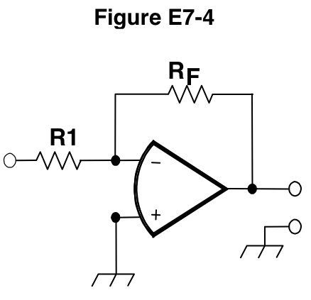
Calculating the gain of an op amp circuit is relatively straightforward. The gain is simply RF/Rin. In figure E7-4 below, Rin = R1. Therefore, the magnitude of voltage gain that can be expected from the circuit in Figure E7-4 when R1 is 10 ohms and RF is 470 ohms is 470/10, or 47. (E7G07) The absolute voltage gain that can be expected from the circuit in Figure E7-4 when R1 is 1800 ohms and RF is 68 kilohms is 68,000/1,800, or 38. (E7G10) The absolute voltage gain that can be expected from the circuit in Figure E7-4 when R1 is 3300 ohms and RF is 47 kilohms is 47,000/3,300, or 14. (E7G11)

Figure E7-4. Operational amplifier circuit

-2.3 volts will be the output voltage of the circuit shown in Figure E7-4 if R1 is 1000 ohms, RF is 10,000 ohms, and 0.23 volts dc is applied to the input. (E7G09) The gain of the circuit will be 10,000/1,000 or 10, and the output voltage will be equal to the input voltage times the gain. 0.23 V x 10 = 2.3 V, but since the input voltage is being applied to the negative input, the output voltage will be negative.

Filed Under: Everything Else Tagged With: filters, op amps

From trade magazines: GE Transistor Manual, analog circuit design, HF op amp filters

April 12, 2012 By Dan KB6NU Leave a Comment

This time, I have two items from EE Times and one from MicroWaves&RF…..Dan


GE Transistor Manual
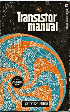
Master the first 170 pages of the venerable GE Transistor Manual and you’ll be a transistor expert.

The GE Transistor Manual. This editorial by Jack Ganssle reminisces about the old GE Transistor Manual. He notes, “It explains transistor theory in a level of detail that my college classes almost a decade later never approached. Read – and understand – the first 170 pages and you’ll be a transistor expert. But no attempt is made to make the subject easy.” One of the comments contains a link that you can use to download your own copy.

UPDATE 5/11/25: Unfortunately, this article doesn’t appear to be online any longer. Fortunately, the GE Transistor Manual still is. Click here.

Book excerpt: Analog Circuit Design— A Tutorial Guide to Applications and Solutions, Part 1. Based on the Application Notes of Linear Technology, this book covers the fundamentals of linear/analog circuit and system design to guide engineers with their design challenges. It includes a broad range of topics, including power-management tutorials, switching-regulator design, linear-regulator design, data conversion, signal conditioning, and high-frequency/RF design. VERY good stuff.

Fabricating HF Opamp Filters. Until recently, op amp filters have generally been restricted to circuits operating below 1 MHz. Recent advances, though, are enabling op amps to amplify at frequencies up to 1 GHz.This article explains how to use them for lowpass filters to 150 MHz.

Filed Under: Books and Magazines, Circuit Design, Electronic Components, Electronics Theory Tagged With: analog, op amps, transistors

Primary Sidebar

No Nonsense Technician Class License Study Guide (for tests given between July 2026 and June 2030)

New No Nonsense Technican Class Study Guide now available!

The 2026 version of my Tech Class study guide is now available, and as always, the PDF version is FREE!. The ePub version costs $11.97, and a Kindle version and paperback version will be available on Amazon shortly.

Click here to get all of my "No Nonsense" study guides.

Also available: The CW Geek's Guide to Having Fun with Morse Code

W5SWL.Com
Retevis Ailunce H1 DMR Radio
DXpander: Cobweb antennas, Laser Cutting

You’ve got mail!

Enter your email address below and get an email every time I publish a new post.

Email


I frequently teach classes to help newcomers get their licenses. The next class will take place on Saturday, February 7, 2026 on the University of Michigan campus. Click here for more information.

If you can't make the class, subscribe to the mailing list to be notified of when the next class will be held.

You can always download my free study guide, and if you have any questions about the classes, or amateur radio in general, please feel free to email me directly.

Support KB6NU.Com

Donate $7.30 and get two of these cool stickers. Measuring 4.25-in. W by 2.75-in. H, it's perfect for your car, your shack, or wherever!

Contact me

If you have a question or comment about one of my blog posts, or a question about any of the material in my study guides, or just a question about ham radio in general, you can email me at [email protected].

Blogs You Should Also Read

  • AE5X: A CW-centric blog from Kingswood, Texas
  • K0LWC Blog
  • LA3ZA Ham Radio Blog
  • Little Radios, Big Fun – WB3GCK
  • Mr. Vacuum Tube's Blog
  • Radio Artisan – K3NG
  • The K0NR Weblog
  • VE3WDM's QRP Ham Radio Blog
  • W2LJ’s Blog

Ham Radio Websites

  • Dashtoons – The Hammin' Comedy by Jeff K1NSS

Podcasts

  • ICQ Podcast
  • Linux in the Ham Schack
  • No Nonsense Amateur Radio Podcast
  • Resonant Frequency Amateur Radio Podcast

Recent Comments

  • Dan KB6NU on Finally, a Loop for 10m.
  • Dan KB6NU on 1930s cards for my collection of QSLs from stations whose callsigns spell words
  • Sean on Finally, a Loop for 10m.
  • Bill Waslo on 1930s cards for my collection of QSLs from stations whose callsigns spell words
  • C M Wetzel KD8TNF on The Wesco BN-1

Meta

  • Log in
  • Entries feed
  • Comments feed
  • WordPress.org

Footer

Copyright © 2026 Daniel M. Romanchik, KB6NU · Log in