• Skip to primary navigation
  • Skip to main content
  • Skip to primary sidebar
  • Skip to footer

KB6NU's Ham Radio Blog

KB6NU's Ham Radio Blog
  • HOME
  • Study Guides
  • Teach a One-Day Tech Class
  • W8SRC Repeater Guide
  • Advertise
  • Hire Me

filters

100, 50, and 25 years ago in QST: Electric filters, SWR meter project, clubs

July 10, 2023 By Dan KB6NU 1 Comment

I love this feature in QST. Not only can you feel the history of amateur radio by reading these articles, many of them still impart useful technical information. Read on and you’ll see what I mean.
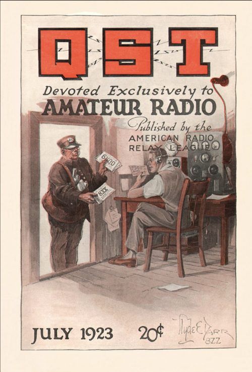
July 1923

The article that I chose from this issue is “Electric Filters” by F.S. Dellenbaugh, Jr. He writes, “Most thing in amateur radio have gotten beyond guesswork; reliable information is available. A glaring exception is the electric wave filter…” He then goes on to give a relatively rigorous explanation of LC filters in many different forms. This is all good stuff and still relevant today.

Also notable in this issue are the articles:

  • Why Inflict Keying Thumps on Your Neighbor? This is perhaps one of the first articles on RFI.
  • Bureau of Standards Explores Short-Wave Region. Early amateurs were relegated to wavelengths below 200 meters, which at that time were thought to be useless for wireless communications. It wasn’t long, however, before radio amateurs proved that to be incorrect.

July 1973

You might thing that the article, A Simple Computing SWR Meter, describes one of the first amateur radio applications of a microprocessor, but  you’d be wrong. Instead, the article gives plans for an SWR/power meter that uses op amps to perform analog computations. The beauty of this approach, according to the authors, is that the SWR reading are independent of the forward power.

July 1998

Two articles in this issue are aimed at helping clubs:

  • Where Radio is Fun. This article brings home the point that to be a successful club, members have to have fun. If your  club is failing, perhaps it’s because you’re not having enough fun.
  • Anatomy of a Special Event Station. I like special event stations, so I’m highlighting this article. The deck reads, “Is your club stuck in a rut? Looking for a project to pep things up? Putting a special event station on the air will definitely pick up the pace….” This article gives a bunch of good advice about running a special event station that’s as relevant today as it was 25 years ago. One such bit of advice is, “Design QSL cards and certificates early in the process—and determine how and when they’ll be printed.”
 

Filed Under: Clubs, Electronic components, EMI/RFI, Special Events, Test Equipment Tagged With: filters, SWR

2020 Extra Class study guide: E7G – Active filters and op-amps: active audio filters; characteristics; basic circuit design; operational amplifiers

February 26, 2020 By Dan KB6NU Leave a Comment

Operational amplifiers, or op-amps for short, are integrated circuits that include a high-gain, direct-coupled differential amplifier with very high input and very low output impedance. They can be used to build amplifiers, filter circuits, and many other types of circuits that do analog signal processing.

QUESTION: What is an operational amplifier? (E7G12)
ANSWER: A high-gain, direct-coupled differential amplifier with very high input impedance and very low output impedance

QUESTION: What is the typical input impedance of an op-amp? (E7G03)
ANSWER: Very high

QUESTION: What is the typical output impedance of an op-amp? (E7G01)
ANSWER: Very low

While the gain of an ideal operational amplifier does not vary with frequency, op amps in the real world do have a finite bandwidth. Some modern op amps can be used at high frequencies, but many of the older ones can’t be used at frequencies above a couple of MHz. To find out if you can use an op amp at the frequency of your signals, check out the gain-bandwidth specification. The gain-bandwidth specification is the frequency at which the open-loop gain of the amplifier equals one.

QUESTION: How does the gain of an ideal operational amplifier vary with frequency? (E7G08)
ANSWER: It does not vary with frequency

QUESTION: What is the gain-bandwidth of an operational amplifier? (E7G06)
ANSWER: The frequency at which the open-loop gain of the amplifier equals one

Ideally, with no input signal, there should be no voltage difference between the two input terminals, and the output voltage should also be zero. Since no electronic component is ideal, there will be a voltage between these two terminals. We call this the input offset voltage. Put another way, the op-amp input-offset voltage is the differential input voltage needed to bring the open-loop output voltage to zero.

QUESTION: What is meant by the “op-amp input offset voltage”? (E7G04)
ANSWER: The differential input voltage needed to bring the open loop output voltage to zero

Because they are active components—that is to say that they amplify—filters made with op amps are called active filters. One use for an op-amp active filter is as an audio filter in a receiver. The values of capacitors and resistors external to the op-amp primarily determine the gain and frequency characteristics of an op-amp RC active filter.

Ringing is one undesirable characteristic of an op-amp filter. One effect of ringing in a filter is that it adds undesired oscillations to the desired signal. One way to prevent unwanted ringing and audio instability in a multi-section op-amp RC audio filter circuit is to restrict both gain and Q.

QUESTION: What is ringing in a filter? (E7G02)
ANSWER: Undesired oscillations added to the desired signal
QUESTION: How can unwanted ringing and audio instability be prevented in an op-amp RC audio filter circuit? (E7G05)
ANSWER: Restrict both gain and Q

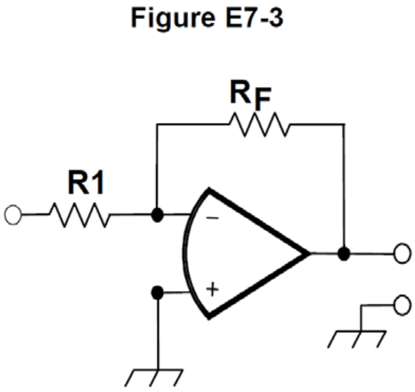
Calculating the gain and output voltage of an op amp circuit is relatively straightforward. The gain is simply RF/Rin. In the op amp circuit shown in Figure E7-3, Rin = R1. The output voltage of a circuit is then the input voltage times the gain.

QUESTION: What magnitude of voltage gain can be expected from the circuit in Figure E7-3 when R1 is 10 ohms and RF is 470 ohms? (E7G07)
ANSWER: 47
If R1 is 10 ohms and RF is 470 ohms, the gain is 470/10, or 47.

QUESTION: What absolute voltage gain can be expected from the circuit in Figure E7-3 when R1 is 1800 ohms and RF is 68 kilohms? (E7G10)
ANSWER: 38
If R1 is 1800 ohms and RF is 68 kilohms, the gain is 68,000/1,800, or about 38.

QUESTION: What absolute voltage gain can be expected from the circuit in Figure E7-3 when R1 is 3300 ohms and RF is 47 kilohms? (E7G11)
ANSWER: 14
If R1 is 3300 ohms and RF is 47 kilohms, the gain is 47,000/3,300, or about 14.

QUESTION: What will be the output voltage of the circuit shown in Figure E7-3 if R1 is 1000 ohms, RF is 10,000 ohms, and 0.23 volts DC is applied to the input? (E7G09)
ANSWER: –2.3 volts
If R1 is 1000 ohms, RF is 10,000 ohms, the gain of the circuit will be 10,000/1,000 or 10, and the output voltage will be equal to the input voltage times the gain. 0.23 V × 10 = 2.3 V, but since the input voltage is being applied to the negative input, the output voltage will be negative.

Filed Under: 2020 Extra Class Study Guide Tagged With: filters, op amps

2020 Extra Class study guide: E7C – Filters and matching networks: types of networks; types of filters; filter applications; filter characteristics; impedance matching; DSP filtering

February 19, 2020 By Dan KB6NU Leave a Comment

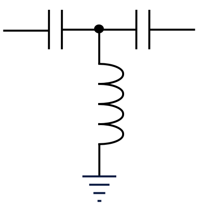
Because the impedance of inductors and capacitors vary with frequency, we often make filters out of them. One of the most common is the T-network filter, so called because it looks like the letter T. An example is shown in figure E7C-1.

T-filter
Figure E7C-1. T-network filter

This particular filter is a T-network high-pass filter. That is to say it will pass frequencies above a certain frequency, called the cutoff frequency, and block frequencies below that frequency. The reason the circuit acts this way is that as the frequency of a signal increases, capacitive reactance decreases and inductive reactance increases, meaning that lower-frequency signals are more likely to be shunted to ground.

QUESTION: Which of the following is a property of a T-network with series capacitors and a parallel shunt inductor? (E7C02)
ANSWER: It is a high-pass filter

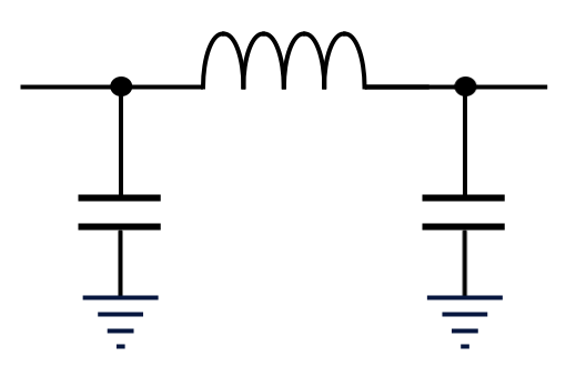
A circuit containing capacitors and inductors can also form a low-pass filter. A low-pass filter is a circuit that passes frequencies below the cutoff frequency and blocks frequencies above it. The circuit shown in figure E7C-2 is called a low-pass, pi filter because it looks like the Greek letter π. The capacitors and inductors of a low-pass filter Pi-network are arranged such that a capacitor is connected between the input and ground, another capacitor is connected between the output and ground, and an inductor is connected between input and output. The reason the circuit acts as a low-pass filter is that as the frequency of a signal increases, capacitive reactance decreases and inductive reactance increases, meaning that higher-frequency signals are more likely to be shunted to ground.

Low-pass pi filter
Figure E7C-2. Pi-network filter

QUESTION: How are the capacitors and inductors of a low-pass filter Pi-network arranged between the network’s input and output? (E7C01)
ANSWER: A capacitor is connected between the input and ground, another capacitor is connected between the output and ground, and an inductor is connected between input and output

Pi networks can also be used to match the output impedance of one circuit to the input impedance of another or the output impedance of a transmitter to the input impedance of an antenna. An impedance-matching circuit transforms a complex impedance to a resistive impedance because it cancels the reactive part of the impedance and changes the resistive part to a desired value. One advantage of a Pi matching network over an L matching network consisting of a single inductor and a single capacitor is that the Q of Pi networks can be varied depending on the component values chosen.

QUESTION: How does an impedance-matching circuit transform a complex impedance to a resistive impedance? (E7C04)
ANSWER: It cancels the reactive part of the impedance and changes the resistive part to a desired value

QUESTION: What is one advantage of a Pi-matching network over an L-matching network consisting of a single inductor and a single capacitor? (E7C12)
ANSWER: The Q of Pi-networks can be controlled

A Pi network with an additional series inductor on the output is called a Pi-L network. They are often used for matching a vacuum-tube final amplifier to a 50-ohm unbalanced output. One advantage a Pi-L-network has over a Pi-network for impedance matching between the final amplifier of a vacuum-tube transmitter and an antenna is that it has greater harmonic suppression than a T network.

QUESTION: Which describes a Pi-L-network used for matching a vacuum tube final amplifier to a 50-ohm unbalanced output? (E7C07)
ANSWER: A Pi-network with an additional series inductor on the output

QUESTION: What advantage does a series-L Pi-L-network have over a series-L Pi-network for impedance matching between the final amplifier of a vacuum-tube transmitter and an antenna? (E7C03)
ANSWER: Greater harmonic suppression

In addition to being used to control the frequency of oscillators, piezoelectric crystals are used to build filters. A crystal lattice filter is a filter with narrow bandwidth and steep skirts made using quartz crystals. The relative frequencies of the individual crystals is the factor that has the greatest effect in helping determine the bandwidth and response shape of a crystal ladder filter. The narrowness of the bandwidth and the steepness of the skirts are sometimes called the filter’s shape factor. The shape factor affects a filter’s ability to reject signals on adjacent frequencies.

QUESTION: What is a crystal lattice filter? (E7C09)
ANSWER: A filter with narrow bandwidth and steep skirts made using quartz crystals

QUESTION: Which of the following factors has the greatest effect on the bandwidth and response shape of a crystal ladder filter? (E7C08)
ANSWER: The relative frequencies of the individual crystals

QUESTION: Which of the following describes a receiving filter’s ability to reject signals occupying an adjacent channel? (E7C11)
ANSWER: Shape factor

Different types of filters have different characteristics. For example, a Chebyshev filter that has a sharp cutoff, but also ripple in the passband. An elliptical filter, on the other hand, has an extremely sharp cutoff with one or more notches in the stop band.

QUESTION: Which filter type is described as having ripple in the passband and a sharp cutoff? (E7C05)
ANSWER: A Chebyshev filter
QUESTION: What are the distinguishing features of an elliptical filter? (E7C06)
ANSWER: Extremely sharp cutoff with one or more notches in the stop band

Often, you’ll choose a filter type for a particular application. For example, a cavity filter would be the best choice for use in a 2 meter repeater duplexer.

QUESTION: Which of the following filters would be the best choice for use in a 2 meter band repeater duplexer? (E7C10)
ANSWER: A cavity filter

Filed Under: 2020 Extra Class Study Guide Tagged With: filters, matching networks

Can you do DSP with an Arduino?

May 12, 2017 By Dan KB6NU 7 Comments

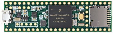
Last fall, I ran across the Kickstarter for the Teensy 3.5 and 3.6. The designer, Paul Stoffregen, bills his Teensies as “powerful microcontrollers for making awesome DIY electronic projects.” The Teensy 3.5 uses a 120 MHz ARM Cortext M-4 processor with a floating-point unit. The Teensy 3.6 has a 180 MHz processor. And, they are Arduino compatible.

The Teensy 3.5 Arduino-compatible microcontroller features a 120 MHz ARM Cortex M-4 processor with a floating point unit. The Teensy 3.6 uses a 180 MHz processor.

“Hmmmm,” I thought to myself, “I bet these processors could do some digital signal processing.” I got really interested when I read about the Teensy Audio Library, which is a toolkit of dozens of audio processing components.

So, I  joined the Kickstarter, and in due course a Teensy 3.5 arrived in my mailbox. Of course, I haven’t yet done anything with it.

Well, yesterday, my friend, Quentin, KD8IPF, sent me an e-mail posted to the 817ND mailing list. It was posted by Gareth, GI1MIC, and includes a couple of links to an open-source project that uses an earlier version of the Teensy to implement an audio DSP add-in for the FT-817. The links include:

  • Code and instructions
  • A video showing the Teensy DSP in action

Gareth notes, “The project is easily modified to run on other rigs or could be fitted inside an amplified speaker.” The latter is what I had in mind.

On the code and instructions page, Gareth links to a tool called TFilter. The web page describes this tool as “a web application that generates linear phase, optimal, equal ripple finite impulse response digital filters. It uses a pure javascript implementation of the Parks–McClellan filter design algorithm.” This tool generates the coefficients used by the Teensy program.

I haven’t really looked at the code yet, but Gareth’s program will switch between a CW filter, a SSB filter, and a third type that I couldn’t make out from the video. In Gareth’s application, the Teensy is embedded into the FT-817, and somehow he is able to use one of the radio’s controls to switch between the different filter types.

Another thing about Gareth’s project is that it uses a Teensy 3.2. The Teensy 3.2 uses a 72 MHz ARM processor, and apparently, that’s quite enough power for audio DSP. The Teensy 3.6 costs $30, while the Teensy 3.2 costs only $20.

I always thought that I’d build mine into a speaker. Not only that, I would like to have a PC application, somewhat like TFilter, that would allow a user to build his own filter on the fly. The program would have to calculate the coefficients on the fly and then download them to the filter.

Filed Under: Building/Homebrew, DSP Tagged With: filters, IIR

2016 Extra Class study guide: E7G – Active filters and op amps

February 10, 2016 By Dan KB6NU Leave a Comment

On July 1, 2020, this post will be obsolete. See the corresponding post from my 2020 version of No Nonsense Extra Class License Study Guide.


Five questions were eliminated from this section, making it a little easier….Dan

E7G – Active filters and op-amps: active audio filters; characteristics; basic circuit design; operational amplifiers

Operational amplifiers, or op-amps for short, are very versatile components. They can be used to build amplifiers, filter circuits, and many other types of circuits that do analog signal processing.

An integrated circuit operational amplifier is a high-gain, direct-coupled differential amplifier with very high input and very low output impedance. (E7G12) The typical input impedance of an integrated circuit op-amp is very high. (E7G03) The typical output impedance of an integrated circuit op-amp is very low. (E7G01)

The gain of an ideal operational amplifier does not vary with frequency. (E7G08) Most op amps aren’t ideal, though. While some modern op amps can be used at high frequencies, many of the older ones can’t be used at frequencies above a couple of MHz.

Ideally, with no input signal, there should be no voltage difference between the two input terminals, and the output voltage should also be zero. Since no electronic component is ideal, there will be a voltage between these two terminals. We call this the input offset voltage. Put another way, the op-amp input-offset voltage is the differential input voltage needed to bring the open-loop output voltage to zero. (E7G04)

Because they are active components—that is to say that they amplify—filters made with op amps are called active filters. The most appropriate use of an op-amp active filter is as an audio filter in a receiver. (E7G06). The values of capacitors and resistors external to the op-amp primarily determine the gain and frequency characteristics of an op-amp RC active filter.

Ringing is one undesirable characteristic of an op-amp filter. One effect of ringing in a filter is that undesired oscillations to be added to the desired signal. (E7G02) One way to prevent unwanted ringing and audio instability in a multi-section op-amp RC audio filter circuit is to restrict both gain and Q. (E7G05)

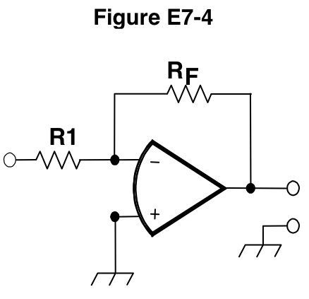
Calculating the gain of an op amp circuit is relatively straightforward. The gain is simply RF/Rin. In figure E7-4 below, Rin = R1. Therefore, the magnitude of voltage gain that can be expected from the circuit in Figure E7-4 when R1 is 10 ohms and RF is 470 ohms is 470/10, or 47. (E7G07) The absolute voltage gain that can be expected from the circuit in Figure E7-4 when R1 is 1800 ohms and RF is 68 kilohms is 68,000/1,800, or 38. (E7G10) The absolute voltage gain that can be expected from the circuit in Figure E7-4 when R1 is 3300 ohms and RF is 47 kilohms is 47,000/3,300, or 14. (E7G11)

Figure E7-4. Operational amplifier circuit

-2.3 volts will be the output voltage of the circuit shown in Figure E7-4 if R1 is 1000 ohms, RF is 10,000 ohms, and 0.23 volts dc is applied to the input. (E7G09) The gain of the circuit will be 10,000/1,000 or 10, and the output voltage will be equal to the input voltage times the gain. 0.23 V x 10 = 2.3 V, but since the input voltage is being applied to the negative input, the output voltage will be negative.

Filed Under: Everything Else Tagged With: filters, op amps

2016 Extra Class study guide: E7C – filters

February 3, 2016 By Dan KB6NU Leave a Comment

On July 1, 2020, this post will be obsolete. See the corresponding post from my 2020 version of No Nonsense Extra Class License Study Guide.


E7C – Filters and matching networks: types of networks; types of filters; filter applications; filter characteristics; impedance matching; DSP filtering

Because the impedance of inductors and capacitors vary with frequency, we often make filters out of them. One of the most common is the T-network filter, so called because it looks like the letter T. An example is shown in figure E7C-1.

T-filter
Figure E7C-1. T-network filter.

This particular filter has the characteristic of being a high-pass filter. That is to say it will pass frequencies above a certain frequency, called the cutoff frequency, and block frequencies below that frequency. A T-network with series capacitors and a parallel shunt inductor has the property of it being a high-pass filter. (E7C02) The reason the circuit acts this way is that as the frequency of a signal increases, capacitive reactance decreases and inductive reactance increases, meaning that lower-frequency signals are more likely to be shunted to ground.

A circuit containing capacitors and inductors can also form a low-pass filter. A low-pass filter is a circuit that passes frequencies below the cutoff frequency and blocks frequencies above it.

Pi is the common name for a filter network which is equivalent to two L networks connected back-to-back with the inductors in series and the capacitors in shunt at the input and output. (E7C11). The circuit shown in figure E7C-2 is called a pi filter because it looks like the Greek letter π.

The capacitors and inductors of a low-pass filter Pi-network are arranged such that a capacitor is connected between the input and ground, another capacitor is connected between the output and ground, and an inductor is connected between input and output. (E7C01) The reason the circuit acts this way is that as the frequency of a signal increases, capacitive reactance decreases and inductive reactance increases, meaning that higher-frequency signals are more likely to be shunted to ground.

Low-pass pi filter
Figure E7C-2. A low-pass filter is made from two shunt capacitors and a series inductance.


Pi networks can also be used to match the output impedance of one circuit to the input impedance of another or the output impedance of a transmitter to the input impedance of an antenna. An impedance-matching circuit transforms a complex impedance to a resistive impedance because it cancels the reactive part of the impedance and changes the resistive part to a desired value. (E7C04) One advantage of a Pi matching network over an L matching network consisting of a single inductor and a single capacitor is that the Q of Pi networks can be varied depending on the component values chosen. (E7C13)

A Pi network with an additional series inductor on the output describes a Pi-L network used for matching a vacuum-tube final amplifier to a 50-ohm unbalanced output. (E7C12) One advantage a Pi-L-network has over a Pi-network for impedance matching between the final amplifier of a vacuum-tube transmitter and an antenna is that it has greater harmonic suppression. (E7C03)

Piezoelectric crystals are also used to build filters. A crystal lattice filter is a filter with narrow bandwidth and steep skirts made using quartz crystals. (E7C15) The relative frequencies of the individual crystals is the factor that has the greatest effect in helping determine the bandwidth and response shape of a crystal ladder filter. (E7C08) A “Jones filter” is a variable bandwidth crystal lattice filter used as part of a HF receiver IF stage. (E7C09)

Different types of filters have different characteristics. For example, a Chebyshev filter is a filter type described as having ripple in the passband and a sharp cutoff. (E7C05) On the other hand, the distinguishing features of an elliptical filter are extremely sharp cutoff with one or more notches in the stop band. (E7C06)

Filters have both amplitude and phase-response characteristics. In some applications, both are important. Digital modes, for example, are most affected by non-linear phase response in a receiver IF filter. (E7C14)

Often, you’ll choose a filter type for a particular application. For example, to attenuate an interfering carrier signal while receiving an SSB transmission, you would use a notch filter. (E7C07) A cavity filter would be the best choice for use in a 2 meter repeater duplexer. (E7C10)

Today, many of these filters are implemented using digital signal processing. The kind of digital signal processing audio filter might be used to remove unwanted noise from a received SSB signal is an adaptive filter. (E7C08) The type of digital signal processing filter might be used to generate an SSB signal is a Hilbert-transform filter. (E7C09)

Filed Under: Electronics Theory Tagged With: filters, pi network

Online chat about filter design

October 21, 2014 By Dan KB6NU 1 Comment

Sorry for the short notice. This just arrived in my e-mail. Might be interesting if you can attend….Dan

Dear Dan,

On Wednesday, October 22nd, at 1:00 p.m. ET (10:00 a.m. PT), join us for a chat session in which we will discuss “Filter Design”.

All real world designs are plagued by noise and other interference signals that are part of our environment including surrounding electronic clocks, RF signals, and more. We sometimes need to go to great efforts to filter out the unwanted signals from the signals critical to the success of our system overall performance. Our expert, Kendall Castor Perry, will be here to answer all of your questions and respond to comments regarding all filter topics.

Kendall Castor Perry, as well as being The Filter Wizard, Kendall is a skilled circuit designer, product engineer, and all-around analog expert. He is a widely published communicator of theory and method in many electronics disciplines. He has spent 21 years designing filters, precision instrumentation, signal processing equipment, and music systems. Then he spent 11 years selling and designing analog semiconductors. Additionally, he has created advanced products to chase signals across many domains, extract the information from them, and do something useful with it. These days, Kendall is with Cypress doing system architecture, product definition, and strategic application analysis for their precision analog and mixed-signal devices.

Sign up now by clicking here to join or to leave an early message! Just click “Reply” or “Post Message” when you get to the site.

Best regards,

Steve Taranovich, Editor in Chief
Planet Analog

Filed Under: Circuit Design Tagged With: filters

Extra Class question of the day: Filter types and applications

September 5, 2012 By Dan KB6NU 3 Comments

Different types of filters have different characteristics. For example, a Chebyshev filter is a filter type described as having ripple in the passband and a sharp cutoff. (E7C05)On the other hand, the distinguishing features of an elliptical filter are extremely sharp cutoff with one or more notches in the stop band. (E7C06)

Filters have both amplitude and phase-response characteristics. In some applications, both are important. Digital modes, for example, are most affected by non-linear phase response in a receiver IF filter. (E7C14)

The Chebyshev filter was named for Pafnuty Chebyshev, whose mathematical work led to the development of these filters. Sometimes filters are named for their circuit topoology. Pi is the common name for a filter network which is equivalent to two L networks connected back-to-back with the inductors in series and the capacitors in shunt at the input and output. (E7C11) When you look at the circuit diagram for a filter of this type, you’ll see that it looks like the Greek letter pi.

Often, you’ll choose a filter type for a particular application. For example, to attenuate an interfering carrier signal while receiving an SSB transmission, you would use a notch filter. (E7C07)

Today, many of these filters are implemented using digital signal processing. The kind of digital signal processing audio filter might be used to remove unwanted noise from a received SSB signal is an adaptive filter. (E7C08) The type of digital signal processing filter might be used to generate an SSB signal is a Hilbert-transform filter. (E7C09)

Some filters are used almost exclusively in a particular application. A cavity filter, for example, would be the best choice for use in a 2 meter repeater duplexer. (E7C10)

Filed Under: Electronics Theory, Extra Class Question of the Day Tagged With: filters

Extra Class question of the day: Receiver performance characteristics

September 2, 2012 By Dan KB6NU 7 Comments

In the past, sensitivity was one of the most important receiver performance specifications. Today, instead of sensitivity, we speak of a receiver’s minimum discernible signal, or MDS. The MDS of a receiver is the minimum discernible signal. (E4C07) This is the weakest signal that a receiver will detect.

One parameter that affects receiver sensitivity is the noise figure. The noise figure of a receiver is the ratio in dB of the noise generated by the receiver compared to the theoretical minimum noise. (E4C04) Lowering the noise figure of a receiver would improve weak signal sensitivity. (E4C08)

A related specification is the noise floor. When we say that the noise floor of a receiver has a value of -174 dBm/Hz, it is referring to the theoretical noise at the input of a perfect receiver at room temperature. (E4C05) If a CW receiver with the AGC off has an equivalent input noise power density of -174 dBm/Hz, the level of an unmodulated carrier input to this receiver would have to be -148 dBm to yield an audio output SNR of 0 dB in a 400 Hz noise bandwidth. (E4C06)

A receiver’s selectivity is the result of a lot of things, including the filters a receiver has. 300 Hz is a desirable amount of selectivity for an amateur RTTY HF receiver. (E4C10)2.4 kHz is a desirable amount of selectivity for an amateur SSB phone receiver.(E4C11)

In addition to a 300 Hz filter and a 2.4 kHz filter, high-end receivers also have filters called roofing filters. A narrow-band roofing filter affects receiver performance because it improves dynamic range by attenuating strong signals near the receive frequency. (E4C13)

Back in the day, when superheterodyne receivers had intermediate frequencies, or IFs, in the 400 – 500 kHz range, image rejection was a problem. If there was a strong signal present on a frequency about two times the IF away from the frequency your receiver was tuned to, you might hear that signal. Accordingly, 15.210 MHz is a frequency on which a station might be transmitting if is generating a spurious image signal in a receiver tuned to 14.300 MHz and which uses a 455 kHz IF frequency. (E4C14)

One solution to this problem is to select an IF higher in frequency. One good reason for selecting a high frequency for the design of the IF in a conventional HF or VHF communications receiver is that it is easier for front-end circuitry to eliminate image responses. (E4C09) A front-end filter or pre-selector of a receiver can also be effective in eliminating image signal interference. (E4C02)

Another way to get rid of image signals is to use a narrow IF filter. An undesirable effect of using too wide a filter bandwidth in the IF section of a receiver is that undesired signals may be heard. (E4C12)

Because most modern transceivers use digital techniques to generate a local oscillator signal to tune a receiver, synthesizer phase noise might be a problem. An effect of excessive phase noise in the local oscillator section of a receiver is that it can cause strong signals on nearby frequencies to interfere with reception of weak signals. (E4C01)

Finally, here are two miscellaneous questions on receiver performance characteristics. Atmospheric noise is the primary source of noise that can be heard from an HF receiver with an antenna connected. (E4C15) Capture effect is the term for the blocking of one FM phone signal by another, stronger FM phone signal. (E4C03)

Filed Under: Extra Class Question of the Day, Receivers Tagged With: filters, image rejection, MDS, noise floor, selectivity, sensitivity

Extra Class question of the day: system noise; electrical appliance noise; line noise; locating noise sources; DSP noise reduction; noise blankers

August 21, 2012 By Dan KB6NU 1 Comment

Noise is often a real problem for radio amateurs. Fortunately, by understanding how noise is generated and how to reduce or eliminate it, noise can be tamed.

Atmospheric noise is naturally-occurring noise. Thunderstorms are a major cause of atmospheric static. (E4E06) There’s not much you can do to eliminate, but you can often use a receiver’s noise blanker to help you copy signals better. Signals which appear across a wide bandwidth (like atmospheric noise) are the types of signals that a receiver noise blanker might be able to remove from desired signals. (E4E03) Ignition noise is one type of receiver noise that can often be reduced by use of a receiver noise blanker. (E4E01)

One undesirable effect that can occur when using an IF noise blanker is that nearby signals may appear to be excessively wide even if they meet emission standards. (E4E09)

Many modern receivers now use digital signal processing (DSP) filters to eliminate noise. All of these choices are correct when talking about types of receiver noise can often be reduced with a DSP noise filter (E4E02):

  • Broadband white noise
  • Ignition noise
  • Power line noise

One disadvantage of using some types of automatic DSP notch-filters when attempting to copy CW signals is that the DSP filter can remove the desired signal at the same time as it removes interfering signals. (E4E12)

While filters can be very effective at reducing noise, it is often better to figure out what is  generating the noise and taking steps to reduce or eliminate the amount of noise generated in the first place. For example, one way you can determine if line noise interference is being generated within your home is by turning off the AC power line main circuit breaker and listening on a battery operated radio. (E4E07) If by doing this you determine that an electric motor is a problem, noise from an electric motor can be suppressed by installing a brute-force AC-line filter in series with the motor leads. (E4E05)

All of these choices are correct when it comes to the cause of a loud roaring or buzzing AC line interference that comes and goes at intervals (E4E13):

  • Arcing contacts in a thermostatically controlled device
  • A defective doorbell or doorbell transformer inside a nearby residence
  • A malfunctioning illuminated advertising display

Sometimes your own equipment may be the cause of received noise. A common-mode signal at the frequency of the radio transmitter is sometimes picked up by electrical wiring near a radio antenna. (E4E08)

The main source of noise in an automobile is the alternator. Conducted and radiated noise caused by an automobile alternator be suppressed by connecting the radio’s power leads directly to the battery and by installing coaxial capacitors in line with the alternator leads. (E4E04)

Personal computer and other digital devices can also generate noise. One type of electrical interference that might be caused by the operation of a nearby personal computer is the appearance of unstable modulated or unmodulated signals at specific frequencies. (E4E14) All of these choices are correct when talking about common characteristics of interference caused by a touch controlled electrical device (with an internal microprocessor) (E4E10):

  • The interfering signal sounds like AC hum on an AM receiver or a carrier modulated by 60 Hz hum on a SSB or CW receiver
  • The interfering signal may drift slowly across the HF spectrum
  • The interfering signal can be several kHz in width and usually repeats at regular intervals across a HF band

Noise can even be generated by the most unlikely things. For example, it is mostly likely that nearby corroded metal joints are mixing and re-radiating the broadcast signals if you are hearing combinations of local AM broadcast signals within one or more of the MF or HF ham bands. (E4E11)

Filed Under: Communications Theory, Extra Class Question of the Day Tagged With: DSP, filters, noise, noise blanker

  • Page 1
  • Page 2
  • Go to Next Page »

Primary Sidebar

No Nonsense Technician Class License Study Guide (for tests given between July 2026 and June 2030)

New No Nonsense Technican Class Study Guide now available!

The 2026 version of my Tech Class study guide is now available, and as always, the PDF version is FREE!. The ePub version costs $11.97, and a Kindle version and paperback version will be available on Amazon shortly.

Click here to get all of my "No Nonsense" study guides.

Also available: The CW Geek's Guide to Having Fun with Morse Code

W5SWL.Com
Retevis Ailunce H1 DMR Radio
DXpander: Cobweb antennas, Laser Cutting

You’ve got mail!

Enter your email address below and get an email every time I publish a new post.

Email


I frequently teach classes to help newcomers get their licenses. The next class will take place on Saturday, October 10, 2026 on the University of Michigan campus. Click here for more information.

If you can't make the class, subscribe to the mailing list to be notified of when the next class will be held.

You can always download my free study guide, and if you have any questions about the classes, or amateur radio in general, please feel free to email me directly.

Support KB6NU.Com

Donate $7.30 and get two of these cool stickers. Measuring 4.25-in. W by 2.75-in. H, it's perfect for your car, your shack, or wherever!

Contact me

If you have a question or comment about one of my blog posts, or a question about any of the material in my study guides, or just a question about ham radio in general, you can email me at [email protected].

Blogs You Should Also Read

  • AE5X: A CW-centric blog from Kingswood, Texas
  • K0LWC Blog
  • LA3ZA Ham Radio Blog
  • Little Radios, Big Fun – WB3GCK
  • Mr. Vacuum Tube's Blog
  • Radio Artisan – K3NG
  • The K0NR Weblog
  • VE3WDM's QRP Ham Radio Blog
  • W2LJ’s Blog

Ham Radio Websites

  • Dashtoons – The Hammin' Comedy by Jeff K1NSS

Podcasts

  • ICQ Podcast
  • Linux in the Ham Schack
  • No Nonsense Amateur Radio Podcast
  • Resonant Frequency Amateur Radio Podcast

Recent Comments

  • Bulin 47 AI on ICQPodcast Episode 485 – World Cup Special Event Station
  • Jesse Alexander on What do you think of this artwork for the ham radio EMF Explorer
  • CADProps on My first go at 3D printing not quite a success
  • Dan KB6NU on A Media Guide to Amateur Radio
  • Steve Stroh N8GNJ on A Media Guide to Amateur Radio

Meta

  • Log in
  • Entries feed
  • Comments feed
  • WordPress.org

Footer

Copyright © 2026 Daniel M. Romanchik, KB6NU · Log in