• Skip to primary navigation
  • Skip to main content
  • Skip to primary sidebar
  • Skip to footer

KB6NU's Ham Radio Blog

KB6NU's Ham Radio Blog
  • HOME
  • Study Guides
  • Teach a One-Day Tech Class
  • W8SRC Repeater Guide
  • Advertise
  • Hire Me

Test Equipment

On the Internet: W2AEW videos, Raspberry Pi programming, classic radio

September 4, 2012 By Dan KB6NU Leave a Comment

Here are a couple of Internet resources to start off the week:

W2AEW on YouTube. Alan, W2AEW, has a great selection of cool videos on YouTube. Some of the latest cover the basics of phase-locked loops, how to zero-beat WWV to check out a frequency counter’s accuracy, and a tutorial on resonant circuits. Good stuff!

Baking Pi – Operating Systems Development. This course, published by the University of Cambridge Computer laboratory, is a free online course that takes you through the basics of operating system development. The Web page notes, “[This course]  is aimed at people aged 16 and upwards, although younger readers may still find some of it accessible, particularly with assistance….I have tried not to assume any prior knowledge of operating systems development or assembly code. It may be helpful to have some programming experience, but the course should be accessible without.”

Classic Exchange. Mac, WQ8U, wrote to the Glowbugs mailing list, “The Classic Exchange (CX) is a low-key, on-air celebration of rigs of days gone by – particularly boat anchors. The latest CX Newsletter is available on the CX web site, as well as details for the next CX on September 16th (for AM and SSB) and September 23nd (for CW). Please enjoy the newsletter, spread the word and join in the fun during the next CX.”
Filed Under: Building/Homebrew, Microcontrollers, On the Internet, Test Equipment, Vintage Radio

Extra Class question of the day: Measurement techniques: Instrument accuracy and performance limitations; probes; techniques to minimize errors; measurement of Q; instrument calibration

August 3, 2012 By Dan KB6NU 1 Comment

One thing about test instruments is that you need to take the readings with a grain of salt. By that, I mean that chances are that the instrument reading is not exactly the value of the parameter you’re measuring. The reason for this is that no instrument is 100% accurate.

Let’s consider frequency counters. Frequency counters are useful instruments for measuring the output frequency of amateur radio transceivers. While a number of different factors can affect the accuracy of an instrument, time base accuracy is the factor that most affects the accuracy of a frequency counter. (E4B01) The time base accuracy of most inexpensive frequency counters is about 1 part per million, or 1 ppm.

Now, let’s see how that affects the accuracy of a frequency measurement. If a frequency counter with a specified accuracy of +/- 1.0 ppm reads 146,520,000 Hz, 146.52 Hz is the most the actual frequency being measured could differ from the reading. (E4B03) Practically, what this means is that while the frequency counter reads 146,520,000 Hz, or 146.52 MHz, the actual frequency of the signal might be as low as 146.519853 Mhz or as high as 146.520147 MHz.

More accurate—and therefore more expensive—frequency counters might have a specified accuracy of .1 ppm. If a frequency counter with a specified accuracy of +/- 0.1 ppm reads 146,520,000 Hz, 14.652 Hz is the most the actual frequency being measured could differ from the reading. (E4B04) This is very accurate for amateur radio work.

Very inexpensive frequency counters might have an accuracy of only 10 ppm. If a frequency counter with a specified accuracy of +/- 10 ppm reads 146,520,000 Hz, 1465.20 Hz is the most the actual frequency being measured could differ from the reading. (E4B05) This might be adequate for amateur radio work, but as you can see, the difference between the frequency counter’s reading and the signal’s actual frequency can be up to ten times as much as with the frequency counter with a 1 ppm accuracy.

In the previous section, we talked about using oscilloscopes to make measurements. One of the factors that affects the accuracy of oscilloscope measurements is the probe being used. You not only have to use a good probe, but you have to know how to use it properly.

When making measurements at RF frequencies, it’s important to connect the probe’s ground connection as close to the location of the measurement as possible. Keeping the signal ground connection of the probe as short as possible is good practice when using an oscilloscope probe. (E4B07) Keeping this connection as short as possible reduces the inductance of the connection, which in turn, makes the measurement more accurate.

Good quality passive oscilloscope probes have an adjustable capacitor in them that needs to be adjusted so that  the probe capacitive reactance is at least nine times  the scope input capacitive reactance. When this capacitor is adjusted properly, we say that the probe is properly compensated, and the scope will display the waveform with as little distortion as possible.

How is the compensation of an oscilloscope probe typically adjusted? A square wave is displayed and the probe is adjusted until the horizontal portions of the displayed wave are as nearly flat as possible. (E4B13) High-quality oscilloscopes will have a special square-wave output specifically for the purpose of compensating probes.

Probably the most common test instrument in an amateur radio station is a voltmeter. The voltmeter may be part of a digital multimeter (DMM) or volt-ohm meter (VOM). DMMs have the advantage of high input impedance, and high impedance input is a characteristic of a good DC voltmeter. (E4B08) The higher the input impedance, the less effect the meter will have on the measurement.

The quality of a VOM is given by the VOM’s sensitivity expressed in ohms per volt. The full scale reading of the voltmeter multiplied by its ohms per volt rating will provide the input impedance of the voltmeter. (E4B12) A higher ohms per volt rating means that it will have a higher input impedance than a meter with a lower ohms per volt rating.

Directional power meters and RF ammeters are two instruments that you can use to make antenna measurements. With a directional power meter, you could measure the forward power and reflected power and then figure out how much power is being delivered to the load and calculate the SWR of the antenna system. For example, 75 watts is the power is being absorbed by the load when a directional power meter connected between a transmitter and a terminating load reads 100 watts forward power and 25 watts reflected power? (E4B06)

With an RF ammeter, you measure the RF current flowing in the antenna system. If the current reading on an RF ammeter placed in series with the antenna feed line of a transmitter increases as the transmitter is tuned to resonance it means there is more power going into the antenna. (E4B09)

There are a number of instruments that you can use to measure the impedance of a circuit. An antenna analyzer is one. Some sort of bridge circuit is another. An advantage of using a bridge circuit to measure impedance is that the measurement is based on obtaining a signal null, which can be done very precisely. (E4B02) 

That’s the principle behind the dip meter. You adjust the meter’s controls so that the reading “dips” to a minimum value. The controls then indicate the resonant frequency. When using a dip meter, don’t couple it too tightly to the circuit under test. A less accurate reading results if a dip meter is too tightly coupled to a tuned circuit being checked. (E4B14)

For some experiments, you’ll want to know not only the resonant frequency of a circuit but also the quality factor, or Q, of the circuit. The bandwidth of the circuit’s frequency response can be used as a relative measurement of the Q for a series-tuned circuit. (E4B15)

Finally, a method to measure intermodulation distortion in an SSB transmitter is to modulate the transmitter with two non-harmonically related audio frequencies and observe the RF output with a spectrum analyzer. (E4B10) The instrument we use to do this is called, oddly enough, a two-tone generator. Typically, these generators provide tones of 700 Hz and 1,900 Hz simultaneously.

Filed Under: Extra Class Question of the Day, Test Equipment

Handheld instrument analyzes antennas and cables, measures power

July 6, 2012 By Dan KB6NU 1 Comment

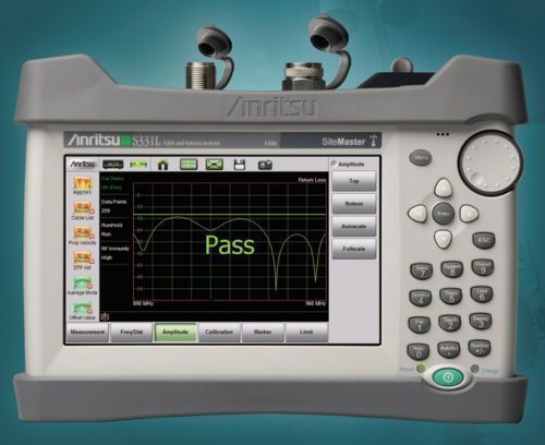
I came across this product announcement in the daily e-mail I get from EE Times. Wouldn’t it be great to have this analyzer? There is one drawback. It costs almost $7k. 

Site Master Handheld Cable & Antenna Analyzer S331L

 Features
  • 2 MHz to 4 GHz Handheld Cable and Antenna Analyzer, impact, dust, and splash resistant
  • Measures power from 50 MHz to 4 GHz
  • More than 8 hours of continuous battery operation
  • Standard built-in InstaCal™ module and Power Meter
  • FlexCal™ maintains calibration with frequency changes
  • Built-in one button Help function
  • 800×480 7” TFT touch screen display and multiple USB ports
  • Internally store >1000 files with fast preview of stored traces
  • Industry standard *.dat format compatible with Line Sweep Tools (LST) and HHST

You can download the product brochure to get an even better idea of what a cool meter this is.

Filed Under: Antennas, Test Equipment

21 Things to Do: Buy a DMM

May 13, 2012 By Dan KB6NU 3 Comments

21 Things to Do After Getting Your Amateur Radio LicenseA digital multimeter, or DMM for short, is the most basic piece of test equipment you can own, and every ham should have one. With a digital multimeter (DMM), you can make voltage, current, and resistance measurements. Some multimeters do even more, but that’s a topic for another book.
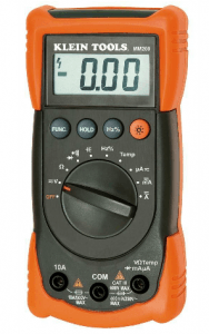
Why do you need a multimeter? Well, the multimeter is the first thing you’ll reach for when you have problems with your equipment. For example, let’s say you go down to your shack, switch on your radio, and nothing. It doesn’t turn on. The first thing you should check in this case is that the power supply is supplying the proper input voltage. To do this, you pull out your DMM, set it to measure voltage, place the probes on the + and – outputs, and verify that the power supply is working.

Klein DMM
This multimeter costs about $50 and features a rugged case that helps prevent damage should you accidentally drop it.

OK, now we’re sure that the power supply is working OK, but the radio still doesn’t power up. The next thing to check is the power cable from the supply to the radio. It’s possible that the cable has an open connection. To check that, you first disconnect the cable from the power supply and from the radio.

This multimeter costs about $50 and features a rugged case that helps prevent damage should you accidentally drop it.Then, set your DMM to measure resistance. Set it on the lowest resistance scale. Connect one test probe to one end of the cable and the other test probe to the other end. The resistance you measure should be very low—less than 2 or 3 ohms. An open connection will register an infinite resistance.

I think you get the picture. Without a DMM, you’re dead in the water. With a DMM, you can figure out what’s wrong and fix it.

There are a wide range of DMMs available. On the low end, you’ll find DMMs at Harbor Freight for $5 or less. On the high end, you could spend $300 or more for a Fluke multimeter. I would advise against both. The $5 multimeters are not very well-made and can be inaccurate. They tend to quit working just when you need them.

The $300 DMMs are great, but you needn’t spend that much. A DMM costing between $30 and $100 will do pretty much all you need to do at this point in your amateur radio adventure, and you can use the money you have left over for other things. You can buy them at any Lowe’s or Home Depot. Ask your friends or Elmer what kind of meter they own and whether or not they would recommend that you buy something similar.

Filed Under: 21 Things to Do After You Get Your Amateur Radio License, Test Equipment

New QRP kit measures power, SWR

March 24, 2012 By Dan KB6NU 4 Comments

From Terry, WA0ITP, via the qrp-l mailing list:

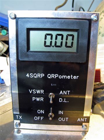
QRP-o-meterThe Four State QRP Group is pleased to announce a new kit, the QRPometer, a sensitive and accurate power/swr meter designed by David Cripe, NMØS.   Complete specifications, assembly manual, and ordering information can be found online.  PayPal is accepted.

The range of accurate power measurement extends down to a low 100 milliwatts.  This kit was conceived to fill a need within the hobby for an inexpensive, highly accurate RF power and VSWR meter for QRP power levels.  With it’s large digital display it makes a very useful addition to your shack.

The QRPometer uses simple analog signal-processing circuitry to provide a set of essential measurement features not previously available in a single unit. High quality, double sided, printed circuit board construction is used, with solder mask and silk screened component reference designators.

All components are  through-hole for easy assembly. NO toroids are required, and all controls  and jacks are PCB mounted. The QRPometer can be constructed by beginners as well as experienced builders. Construction time is approximately 3 hours, depending on experience level. The only equipment required for calibration is a digital voltmeter, and a QRP transmitter..

All proceeds  go to fund OzarkCon.  As always, thank you for supporting the Four State QRP Group.

Filed Under: Antennas, Kits, Test Equipment

Extra Class question of the day: spectrum analyzers and oscilloscopes

February 12, 2012 By Dan KB6NU Leave a Comment

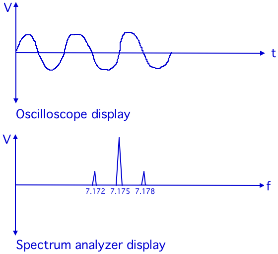
Two instruments that amateur radio operators frequently use when experimenting or when debugging equipment are the oscilloscope and the spectrum analyzer. How does a spectrum analyzer differ from an oscilloscope? A spectrum analyzer displays signals in the frequency domain; an oscilloscope displays signals in the time domain. (E4A01) What this means is that an oscilloscope will show you have the amplitude of a signal changes with time, while a spectrum analyzer shows you how the amplitude of a signal changes with frequency. The drawing below shows typical displays from an oscilloscope and a spectrum analyzer.

Spectrum analyzers and oscilloscopes
The oscilloscope shows how a signal's amplitude changes with time, while a spectrum analyzer shows how a signal's amplitude changes with frequency.


Because the spectrum analyzer shows how the amplitude of a signal changes with frequency, amplitude is the parameter a spectrum analyzer would display on the vertical axis. (E4A03) Frequency is the parameter a spectrum analyzer would display on the horizontal axis. (E4A02)

Spectrum analyzers are very useful for troubleshooting problems. For example, a spectrum analyzer is used to display spurious signals from a radio transmitter. (E4A04) A spectrum analyzer is also used to display intermodulation distortion products in an SSB transmission. (E4A05) The reason for this is that in both of these cases we are looking for signals that are being erroneously generated.

Whenever frequency is an important part of the measurement, you want to use a spectrum analyzer, if one is available. All of these choices are correct when talking about parameters than can be determined with a spectrum analyzer (E4A06):

  • The degree of isolation between the input and output ports of a 2 meter duplexer
  • Whether a crystal is operating on its fundamental or overtone frequency
  • The spectral output of a transmitter

Because spectrum analyzers are sensitive instruments, you need to be cautious when using them. For example, an important precaution to follow when connecting a spectrum analyzer to a transmitter output is to attenuate the transmitter output going to the spectrum analyzer. (E4A12) Not doing so could damage the spectrum analyzer because its input circuits are not designed to handle high power.

Despite all this talk about spectrum analyzers, the oscilloscope is actually the more versatile instrument,  and will be more useful than the spectrum analyzer for most radio amateurs. For example, the oscilloscope is the instrument used for detailed analysis of digital signals. (E4A11) You can make a number of digital-signal measurements with a scope, including rise time and fall time, as well as analyze how two or more digital signals change in time with regard to one another.

Filed Under: Extra Class Question of the Day, Test Equipment

What’s your favorite test instrument?

January 20, 2012 By Dan KB6NU 11 Comments

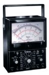
Simpson Model 60 VOM
The venerable Simpson Model 60 VOM has been in production for more than 60 years.

In the Test&Measurement World group on LinkedIn, editor Martin Rowe asks, “What’s your favorite test instrument”? He gets some interesting answers, but the two top vote-getters are the Bird Model 43 Wattmeter and the Simpson Electric Model 60 VOM (see right).

About the Bird wattmeter, one engineer said, “That’s easy – The Bird Model 43 Wattmeter. No other instrument has been in production, in its original design, for so long. Since 1952, which makes next year 2012 its 60th anniversary. Also, it must be the simplest, most rugged instrument ever produced. We regularly see Model 43 Wattmeters returned to us for calibration that are 30-40 years old, still working and, when they leave our facility, as accurate as the day they first came of the production line in Solon, Ohio.”

About the Simpson VOM, another replied, “My favorite test instrument of all time is the Simpson 260. I used it back in the 1970s while serving in the US Navy. It is rugged, easy to use, and does the job!”

Those are really two classics, and either is a great choice. But, what do  you think? What’s your favorite test instrument?

Filed Under: Test Equipment

From the Twittersphere

January 14, 2012 By Dan KB6NU Leave a Comment

The Twittersphere is kind of like the ionosphere. It helps you make contact with other hams and brings you news from far and wide. Here are a few interesting links that I found on Twitter in the last day or so:

Global Pirate HF Weekend 14-15.1.2012.  This station lists pirate SW radio stations that it expects to be on the air this weekend. They include one using the callsign WEMP. Look for it between 15.005 – 15.095 MHz. They’ll be broadcasting with 100 W to Europe: 12.00 – 16.00 UTC – (check 15.010 or 15.040 or 15.090 MHz).

The Evil Mad Scientist Laboratories Zener Diode Tutorial. Confused about zener diodes and how they work? Read this.

Monitor your Ham Radio transmitter with an oscilloscope. In this video, Alan, W2AEW builds a little adapter that lets you connect your transmitter output to a scope input so that you can see how clean its output is.

Filed Under: Electronic Components, SWLing, Test Equipment

Hack a Day: Use an Arduino to Measure Inductance

July 26, 2011 By Dan KB6NU Leave a Comment

It’s been over a year since I built an Arduino microcontroller at our club’s annual construction night, and I still haven’t done anything with it. I’ve had a couple of ideas, including a keyer that would actuate accept paddle inputs and actuate a solenoid that would open and close a straight key, but just haven’t had the time or inclination to actually put something together.

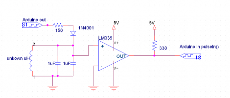
Well, here’s a cool idea as to how to use an Arduino to measure inductance.

Measure inductance with an ArduinoA signal in from the Arduino excites an LC circuit. The L in the LC circuit is our unknown inductor. The output of the LM339 is a square wave whose frequency is proportional to the L of the LC circuit. Measure that frequency with the Arduino and you know the unknown inductance. Of course, calibrating this thing could be a bit tricky, but it might be fun to play with.
Filed Under: Building/Homebrew, Microcontrollers, Test Equipment

Device Tests PowerPole Outlets

June 16, 2011 By Dan KB6NU 1 Comment

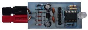
PowerPole Voltage and Polarity CheckerI just found a link to this unique little device and had to blog about it right away.  The PowerPole Polarity and Voltage Tester is similar to one of those little devices that you plug into an AC outlet that tells you if the outlet is wired correctly. Except that you plug this device into an unknown PowerPole outlet.

What  surprised me is that this little device actually uses a microcontroller to measure the voltage. I guess that I really shouldn’t be surprised, though. Microcontrollers come in very small packages now, and programming them is very simple to do .

Because microcontroller are programmable, you could extend the functionality of this device. For example, you could add a small alpha-numeric display or more LEDs to indicate different voltage ranges.

While the circuit is very simple, and is easily fabricated on some perfboard, the author of this Instructables project, has indicated that he intends to make a PC board and kit available. I’ve e-mailed him about this, and will report on what he has to say about price and availability.

Another thought that occurs to me is that I could make one of these with the Arduino that’s been languishing beneath my workbench for the last year or so. Basically, I’d just take the front end circuitry from this project and connect it up to my Arduino. I’d have to do some programming, but I think I can handle that. :)


Filed Under: Building/Homebrew, Test Equipment

  • « Go to Previous Page
  • Page 1
  • Interim pages omitted …
  • Page 11
  • Page 12
  • Page 13
  • Page 14
  • Page 15
  • Go to Next Page »

Primary Sidebar

No Nonsense Technician Class License Study Guide (for tests given between July 2026 and June 2030)

New No Nonsense Technican Class Study Guide now available!

The 2026 version of my Tech Class study guide is now available, and as always, the PDF version is FREE!. The ePub version costs $11.97, and a Kindle version and paperback version will be available on Amazon shortly.

Click here to get all of my "No Nonsense" study guides.

Also available: The CW Geek's Guide to Having Fun with Morse Code

W5SWL.Com
Retevis Ailunce H1 DMR Radio
DXpander: Cobweb antennas, Laser Cutting

You’ve got mail!

Enter your email address below and get an email every time I publish a new post.

Email


I frequently teach classes to help newcomers get their licenses. The next class will take place on Saturday, February 7, 2026 on the University of Michigan campus. Click here for more information.

If you can't make the class, subscribe to the mailing list to be notified of when the next class will be held.

You can always download my free study guide, and if you have any questions about the classes, or amateur radio in general, please feel free to email me directly.

Support KB6NU.Com

Donate $7.30 and get two of these cool stickers. Measuring 4.25-in. W by 2.75-in. H, it's perfect for your car, your shack, or wherever!

Contact me

If you have a question or comment about one of my blog posts, or a question about any of the material in my study guides, or just a question about ham radio in general, you can email me at [email protected].

Blogs You Should Also Read

  • AE5X: A CW-centric blog from Kingswood, Texas
  • K0LWC Blog
  • LA3ZA Ham Radio Blog
  • Little Radios, Big Fun – WB3GCK
  • Mr. Vacuum Tube's Blog
  • Radio Artisan – K3NG
  • The K0NR Weblog
  • VE3WDM's QRP Ham Radio Blog
  • W2LJ’s Blog

Ham Radio Websites

  • Dashtoons – The Hammin' Comedy by Jeff K1NSS

Podcasts

  • ICQ Podcast
  • Linux in the Ham Schack
  • No Nonsense Amateur Radio Podcast
  • Resonant Frequency Amateur Radio Podcast

Recent Comments

  • Michael Burkhardt on One lump or two (or three)?
  • Eric on POTA notes, 7/27/26
  • Steve KB3JC on How to “ragchew” on CW
  • Dan KB6NU on Yaesu FT-710: What’s the big deal?
  • Andrei on Yaesu FT-710: What’s the big deal?

Meta

  • Log in
  • Entries feed
  • Comments feed
  • WordPress.org

Footer

Copyright © 2026 Daniel M. Romanchik, KB6NU · Log in