• Skip to primary navigation
  • Skip to main content
  • Skip to primary sidebar
  • Skip to footer

KB6NU's Ham Radio Blog

KB6NU's Ham Radio Blog
  • HOME
  • Study Guides
  • Teach a One-Day Tech Class
  • W8SRC Repeater Guide
  • Advertise
  • Hire Me

Test Equipment

From the trade magazines: litz wire, vector network analyzers, SDR

July 5, 2013 By Dan KB6NU Leave a Comment

Another selection of amateur radio related items appearing recently in the electronic engineering trade publications.

Litz wire and other component cleverness
If you’re not familiar with it, litz wire is not named after a person or a place. It’s short for Litzendraht, the German term for braided, stranded, or woven wire. It’s a very clever solution to the problems and inefficiencies caused by the skin effect — as the frequency of the current that a wire carries increases, the current tends to go to the outside of the wire.

Vector network analyzers support versatile testing
Among the most valuable of RF/microwave test tools is the vector network analyzer (VNA), which can measure amplitude and phase with frequency. VNAs have long become associated with the measurements of complex impedance parameters—such as scattering (S) parameters—using the test data to design efficient impedance matching networks for the optimum transmission of high-frequency signals through active and passive devices and networks. At present, VNAs are available from both well-known and not-so-well-known instrument manufacturers, in both bench top and portable configurations for making measurements on high-frequency (HF) through millimeter-wave-frequency signals.

Integrated RF analog, multi-standard, software-defined radio receivers
The scaling of CMOS technologies typically has a great impact on analog design. The most severe consequence is the reduction of the voltage supply. Imec and Renesas have managed to put a complete, high-performance SDR (Software Defined Radio) receiver into a 28nm CMOS process with a 0.9V power supply. The IC has everything except a PLL on a single monolithic chip. (See Figure 1.) This is an impressive integration of analog functionality.

Filed Under: Electronic Components, Software-Defined Radio (SDR), Test Equipment

From my Twitter feed: no code test, Contest U, iPhone sig gen

June 12, 2013 By Dan KB6NU Leave a Comment

Jeff K1NSSJeff K1NSS @K1NSS
NO CODE TEST! If that don’t grab ’em, I argue MIGHT AS WELL! Outreach according to http://www.dashtoons.com  #hamr #qrp pic.twitter.com/vAngtDNmmu

Matt MaszczakMatt Maszczak @rocknrollriter
For the new or newer op looking into contesting: http://www.arrl.org/news/view/dayton-contest-university-videos-available-on-youtube?utm_source=twitterfeed&utm_medium=facebook …

Jacob BeningoJacob Beningo @Jacob_Beningo
Turn a Smart Phone into a Signal Generator | EDN http://www.edn.com/electrical-engineer-community/industry-blog/4416138/1/Turn-a-Smart-Phone-into-a-Signal-Generator … via @edncom

Filed Under: Classes/Testing/Licensing, Contests, Test Equipment

From the trade magazines: capacitors, inductors, radio architectures

May 22, 2013 By Dan KB6NU Leave a Comment

Temperature and voltage variation of ceramic capacitors. Read the data sheet! This tutorial explains how ceramic capacitor type designations, such as X7R and Y5V, imply nothing about voltage coefficients. You must check the data sheet to really know, how a specific capacitor will perform under temperature and voltage.

Circuit measures capacitance or inductance. You don’t need a fancy LC meter to measure capacitance or inductance. This short article show you how to do it with a function generator, multimeter, frequency counter, and an oscilloscope. Hmmmmm. By the time you get that all lashed up, it might have been quicker to just buy one of these LC meters from China.

Understand Radio Architectures. This is the first in a series of excerpts from the book RF Circuit Design, 2e by Christopher Bowick. Even though this appears in an engineering trade magazine, some of this is pretty basic stuff. You even get a schematic for a crystal radio!

Filed Under: Electronic Components, Electronics Theory, Test Equipment

From my Twitter feed: HF receivers, voltage reference, FDIM

April 11, 2013 By Dan KB6NU Leave a Comment

ke9v
A History of HF Receivers | Smoke Curlshttp://t.co/A2uHc38mic #hamr


dangerousproto
Erl’s voltage referencehttp://t.co/X0MOESc8BO

I need to build one of these……Dan


qrparciFDIM 2013 (Dayton) – Full seminar schedule now online http://t.co/9eWdTI0FEx #hamr#qrp #hamvention
I’ll be attending FDIM. If you see me, say hi….Dan

Filed Under: Gear/Gadgets, QRP, Receivers, Test Equipment

You need a digital multimeter

April 1, 2013 By Dan KB6NU 5 Comments

I’ve decided that my next book is going to be about multimeters. Here’s a draft of the first chapter…Dan

Digital multimeters, or DMMs, are the most commonly-used test instruments by electronics engineers, technicians, and hobbyists to design, build, and troubleshoot electronic circuits. If you work with electronics or electrical circuits, either as a professional or as a hobbyist, you need a digital multimeter. Without one, it’s almost impossible to adjust or troubleshoot circuits.

Let me give you an example. About a year ago, my brother, Michael, decided that he was going to purchase a very-used shuffle bowling machine at an estate sale. This is the kind of coin-operated machine that you would often in bars. Put in a dime and it would allow you to “bowl” a game.

The unit he purchased was built in the late 1950s. Needless to say, it needed a lot of work. Before he actually paid for it, Michael asked me if I would help him fix it, and I said sure. It looked like it would be a lot of fun to get it running again.

The first thing that I advised him to do-once he got the machine home-was to buy a digital multimeter. With the digital multimeter, he was able to:

  • Check the voltage across the transformer secondary windings to ensure that the transformer was still good.
  • Check the continuity of the many solenoids in the machine to ensure that they were not shorted or open.
  • Check the switches to make sure that they operated properly.
  • Check the continuity of the wires in the cables connecting all the switches, solenoids, and indicators.
  • And make many other measurements.

Without the digital multimeter, it would have been next to impossible to get the machine working again.

If you’re an amateur radio operator, you’ll need a multimeter to measure the output of your power supply and set it properly. You’ll need it to measure the resistance of the resistor that you’re going to insert in the printed circuit board of the kit you’re building. You’re going to need it to make sure that you haven’t shorted out your coax after you’ve installed a PL-259 connector on it. I have used mine for all of these measurements and more.

If you’re a homeowner, you can use a multimeter to check that the voltage present at an AC wall socket is really 117 VAC. You can also use it to make sure that the socket is wired properly.  You can also use it to tell if a switch is working properly or if a circuit is wired properly.

What is a digital multimeter?
Simply put, a DMM is a test instrument that allows the user to measure voltage, current, and resistance, the three primary characteristics of an electrical circuit. While some DMMs may have other functions, measuring voltage–both direct current (DC) voltage and alternating current (AC) voltage, AC and DC current, and resistance are the most basic.

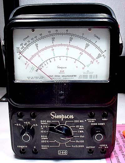
It’s called a “digital” multimeter because it uses digital electronics technology, rather than analog electronics technology to make measurements. Older “analog” multimeters used an electro-mechanical meter, like the one shown below, to indicate the value of the voltage, current, or resistance being measured. To make the measurement, you had to note how far the meter’s needle had deflected and then read the value from a scale printed on the face of the meter. A digital multimeter, on the other hand, displays a number on its LCD or LED display.

The venerable Simpson 260 analog multimeter uses an electromechanical meter to read out measured values

The difference between the two technologies is very similar to the difference between mechanical clocks and digital clocks. With a mechanical clock or watch, you have to note the positions of the two hands and then estimate the actual time. With a digital clock, you simply read the numbers. Both tell you the time, though.

While many old-timers swear by their analog meters, and while there are a few applications for which an analog meter is preferable to a digital meter, if you’re in the market for a multimeter, you want to buy a digital one. One reason for this is that most analog meters—at least ones that are any good—are really expensive. This generally makes instruments made with an analog meter more expensive than a digital multimeter that offers similar performance.

A digital multimeter will open up the world of electricity and electronics to you. With a digital multimeter, you’ll be able to make measurements that will show you how electrical and electronic circuits really work. And with that knowledge, you’ll save money as a homeowner and have more fun as an electronics hobbyist.

Filed Under: Test Equipment Tagged With: digital multimeter, DMM

From the trade magazines, selecting crystals, understanding measurement uncertainty, Maxwell’s equations

February 13, 2013 By Dan KB6NU 2 Comments

Another selection of articles from the electronics engineering trade magazines……Dan

Selecting Crystals For Stable Oscillators
Understanding how quartz-crystal resonators operate can lead to designing crystal oscillators with improved stability and better noise performance.

Tutorial on Maxwell’s Equations
There’s a lot of math here, but cracking Maxwell’s equations will give you a lot of insight on how radio works. Registration required.

Understand Uncertainty For Better Test Accuracy
How sure are you of that measurement you just made with your multimeter or wattmeter? This article might open your eyes as to the accuracy of your measurements.


Filed Under: Electronics Theory, Test Equipment

From the trade magazines: signal generators, refurbishing ICs?

February 7, 2013 By Dan KB6NU Leave a Comment

This edition of “From the trade magazines” includes items from RF&Microwaves, Radio World, and EE Times………Dan

The Fundamentals Of Signal Generation. Signal generators have become indispensable tools for producing the test signals required by today’s engineers to successfully develop and test their devices and systems.


Jim Charlong operates the amateur radio station at the Marconi National Historic Site of Canade.

Dedicated Ham Keeping Morse Code Alive. Operated by Parks Canada, the Marconi National Historic Site of Canada  features a museum with a model of the original transmission structure, a historical multimedia display and tour — and Jim Charlong, who keeps the site’s Morse code broadcast legacy alive and on the air. Charlong is a dedicated Morse code operator with 50 years’ experience under his “fist” — fist being a ham radio term that describes the signature speed and style of an operator’s key-tapping skills. Since the Marconi museum opened in July 1989, he has volunteered as its resident Morse code radio operator. From his “radio shack” inside the museum, Charlong regularly communicates with other Morse code operators around the world.

Smoke re-concentrator refurbishes blown electronic components. I think that perhaps they jumped the gun with this article. I’m thinking that an April 1 publication date would have been more appropriate.

Filed Under: CW, Test Equipment Tagged With: humor

How do you choose an antenna analyzer?

January 22, 2013 By Dan KB6NU 13 Comments

A reader recently e-mailed me:

In the past you told me you started with the Autek RF-1, and later moved to the Palstar ZM-30. I am finally getting around to thinking about purchasing an antenna analyzer, but I am stumped by the choices. In order of increasing purchase price this is what I’ve turned up:

  • Autek RF-1 – $139.95
  • Autek RF-5 – $229.95
  • Rig Expert AA-54 – $340.00
  • Palstar ZM-30 $399.99
  • W4RT Electronics MiniVNA $399.99
  • Rig Expert AA-230PRO $690.00
  • Timewave Technology TZ-900S $899.99

How does one decide? Where does one go to find out the differences? Other than asking a fellow ham, how does one find out which one is the best antenna analyzer without paying an arm and a leg (unless the feature(s) so purchased are deemed worth the cost)?

Thanks! 73

He actually missed several other good choices:

  • Autek VA1 – $199. This is actually the antenna analyzer that I first purchased.
  • MFJ 259B – $240. This is arguably the most popular antenna analyzer on the market. MFJ has several other models with different feature sets.
  • YouKits FG-01 – $250. This is a very cute, little analyzer with a small graphical display. It seems kind of expensive, but the graphical display might be worth it.
  • Comet CAA500 – $450.

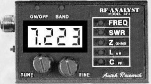
So, how do you choose just one from this list? Well, I think the first thing that you have to ask yourself is how you’re going to use the analyzer. If all you’re going to do is to check the SWR of your HF dipoles, then buy the Autek RF-1. It’s the least expensive unit, is reasonably accurate, and is small and lightweight, making it easy to use outside where your antennas are located.

Autek RF-1
The Autek RF-1 is inexpensive, and its small size makes it easy to use outdoors where your antennas are.

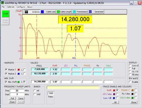
If you want to do some more serious frequency analysis, then you should be looking at the W4RT miniVNA or, if you have more cash, the Timewave TZ-900s. These instruments can help you do a lot more in-depth analysis of your antenna system. The figure below, for example, shows a plot generated by the miniVNA software. It shows the SWR of a multi-band vertical antenna from 3 – 33 MHz.

miniVNa display
For more sophisticated frequency analysis, consider the miniVNA. It uses a computer to generate graphs like this.

Some antenna analyzers do more than just SWR. For example, what sold me first on the Autek VA1 and then on the Palstar was that they also measured reactance. So, you can use the antenna analyzer as an LC meter as well. Palstar also says that you can use the ZM-3 as a low-level signal source.

Next, you need to consider what bands you’ll be using it on. Many antenna analyzers only cover the HF bands. That’s a bummer if you like operating 6m, or like to experiment with VHF/UHF antennas. A friend of mine bought the Palstar antenna analyzer after talking to the company at Dayton. At the time, they said that they were planning to come out with a model that covered 6m, as well as the HF bands.

Unfortunately, they never did come out with a 6m version, and he was sorely disappointed. He ended up buying a miniVNA instead.

Asking your fellow hams about the antenna analyzers they have is actually a good way to figure out what’s best for you. If you ask nicely, they might even let you borrow their analyzers or come over and show you how it works on your antennas.

Reading the reviews on eHam is also a good way to gather information before making a purchase like this. You certainly have to take the reviews there with a grain of salt, but if several reviewers mention a particularly good or particularly bad feature of a product, then it’s certainly something worth taking a hard look at.

If you’re new to the hobby, starting out small and working your way up might be a good strategy. You could buy one of the less expensive models and get used to how they work,  then sell it and make the leap to a more sophisticated unit. The way things are going, you should be able to sell your first antenna analyzer for at least 80% of what you paid for it.

Whatever you do, don’t fall victim to “paralysis by analysis.” Go ahead and buy one and start using it. This is a learn by doing hobby after all.

Filed Under: Antennas, Gear/Gadgets, Test Equipment

DMM tips, anyone?

November 25, 2012 By Dan KB6NU 8 Comments

Now that I’ve published the No-Nonsense Extra Class License Study Guide, I’ve been thinking about what my next book should be. At this point I’m leaning towards The No-Nonsense Guide to Digital Multimeters. I have even started outlining the book:

  • What is a digital multimeter?
    • Compare to analog multimeter
  • Digital multimeter basics
    • Measurement types
    • Inputs
    • Range
    • Zero
    • Safety
  • Making measurements with a DMM
    • Simple DC circuit
      • voltage
      • current
    • AC measurements
      • true RMS
    • Resistance
  • Tips for Choosing a DMM
  • Hints and Kinks

I’d love to get your feedback on this.

What else should I add to this outline?

What would you like to know about DMMs?

Do you have any tips for using DMMs that you’d like to share with others? (If I use your tip in the book, I’ll send you a free copy when it’s finished.)

Filed Under: Books and Magazines, Test Equipment

Extra Class question of the day: Frequency counters and markers

September 20, 2012 By Dan KB6NU 2 Comments

To measure the frequency of a signal, you use an instrument called a frequency counter. The purpose of a frequency counter is to provide a digital representation of the frequency of a signal.(E7F09) A frequency counter counts the number of input pulses occurring within a specific period of time. (E7F08)

To accurately measure high-frequency signals digitally, you need a highly stable and accurate frequency source, called the time base. The time base provides an accurate and repeatable time period, over which you count the number of pulses of the test signal. The accuracy of the time base determines the accuracy of a frequency counter. (E7F07)

An alternate method of determining frequency, other than by directly counting input pulses, that is used by some counters is period measurement plus mathematical computation. (E7F10) An advantage of a period-measuring frequency counter over a direct-count type is that it provides improved resolution of low-frequency signals within a comparable time period. (E7F11)

You also need an accurate and stable time base to generate and receive microwave signals. All of these choices are correct when talking about techniques for providing high stability oscillators needed for microwave transmission and reception: (E7F05)

  • Use a GPS signal reference
  • Use a rubidium stabilized reference oscillator
  • Use a temperature-controlled high Q dielectric resonator

If you want to measure a signal whose frequency is higher than the maximum frequency of your counter, you might use a prescaler. The purpose of a prescaler circuit is to divide a higher frequency signal so a low-frequency counter can display the input frequency. (E7F01) A prescaler would, for example, be used to reduce a signal’s frequency by a factor of ten. (E7F02)

You might use a decade counter digital IC in a prescaler circuit. The function of a decade counter digital IC is to produce one output pulse for every ten input pulses. (E7F03)

In some cases, you might use a flip-flop. Two flip-flops must be added to a 100-kHz crystal-controlled marker generator so as to provide markers at 50 and 25 kHz. (E7F04) The purpose of a marker generator is to provide a means of calibrating a receiver’s frequency settings. (E7F06) You mostly find marker generators in older, analog receivers.

Filed Under: Digital Logic, Extra Class Question of the Day, Test Equipment

  • « Go to Previous Page
  • Page 1
  • Interim pages omitted …
  • Page 10
  • Page 11
  • Page 12
  • Page 13
  • Page 14
  • Page 15
  • Go to Next Page »

Primary Sidebar

No Nonsense Technician Class License Study Guide (for tests given between July 2026 and June 2030)

New No Nonsense Technican Class Study Guide now available!

The 2026 version of my Tech Class study guide is now available, and as always, the PDF version is FREE!. The ePub version costs $11.97, and a Kindle version and paperback version will be available on Amazon shortly.

Click here to get all of my "No Nonsense" study guides.

Also available: The CW Geek's Guide to Having Fun with Morse Code

W5SWL.Com
Retevis Ailunce H1 DMR Radio
DXpander: Cobweb antennas, Laser Cutting

You’ve got mail!

Enter your email address below and get an email every time I publish a new post.

Email


I frequently teach classes to help newcomers get their licenses. The next class will take place on Saturday, February 7, 2026 on the University of Michigan campus. Click here for more information.

If you can't make the class, subscribe to the mailing list to be notified of when the next class will be held.

You can always download my free study guide, and if you have any questions about the classes, or amateur radio in general, please feel free to email me directly.

Support KB6NU.Com

Donate $7.30 and get two of these cool stickers. Measuring 4.25-in. W by 2.75-in. H, it's perfect for your car, your shack, or wherever!

Contact me

If you have a question or comment about one of my blog posts, or a question about any of the material in my study guides, or just a question about ham radio in general, you can email me at [email protected].

Blogs You Should Also Read

  • AE5X: A CW-centric blog from Kingswood, Texas
  • K0LWC Blog
  • LA3ZA Ham Radio Blog
  • Little Radios, Big Fun – WB3GCK
  • Mr. Vacuum Tube's Blog
  • Radio Artisan – K3NG
  • The K0NR Weblog
  • VE3WDM's QRP Ham Radio Blog
  • W2LJ’s Blog

Ham Radio Websites

  • Dashtoons – The Hammin' Comedy by Jeff K1NSS

Podcasts

  • ICQ Podcast
  • Linux in the Ham Schack
  • No Nonsense Amateur Radio Podcast
  • Resonant Frequency Amateur Radio Podcast

Recent Comments

  • Michael Burkhardt on One lump or two (or three)?
  • Eric on POTA notes, 7/27/26
  • Steve KB3JC on How to “ragchew” on CW
  • Dan KB6NU on Yaesu FT-710: What’s the big deal?
  • Andrei on Yaesu FT-710: What’s the big deal?

Meta

  • Log in
  • Entries feed
  • Comments feed
  • WordPress.org

Footer

Copyright © 2026 Daniel M. Romanchik, KB6NU · Log in