• Skip to primary navigation
  • Skip to main content
  • Skip to primary sidebar
  • Skip to footer

KB6NU's Ham Radio Blog

KB6NU's Ham Radio Blog
  • HOME
  • Study Guides
  • Teach a One-Day Tech Class
  • W8SRC Repeater Guide
  • Advertise
  • Hire Me

Electronics Theory

Cleaning off my desk: “F” is for frequency

September 1, 2014 By Dan KB6NU Leave a Comment

I make lots of notes as I Twitter and read my e-mail. I have so many notes about interesting things piled up on my desk, that I really need to start cleaning it up and moving the notes either here to my blog or maybe to Evernote.

Having said that, I’ve written in the past about the need for a study guide for kids. We still need something like this in amateur radio, but there are now books and videos that can teach kids about electronics. One of the books available is The Manga Guide to Electricity.

As far as videos go, Adafruit, has published a number of YouTube videos they call the Circuit Playground. I’ve just watched the video “F is for frequency” (see below). It’s really pretty good, and there is a whole series of them. Adafruit also has a coloring book, E is for Electronics, to go along with the videos. If you have kids, you should check them out.

Filed Under: Electronics Theory, Kids

From my Twitter feed: diode ring mixers, TAPR news, SDR SA

August 28, 2014 By Dan KB6NU Leave a Comment

Stefano_NVR's avatarDr. NVR @Stefano_NVR
How a Diode Ring Mixer works | Mixer operation theory and measurement: youtu.be/junuEwmQVQ8


ke9v's avatarJeff Davis
Summer 2014 TAPR PSR Journal Available –> tapr.org/psr/psr126.pdf #hamradio


EDNcom's avatarEDN.com @EDNcom
RT @measurementblue: Michael Dunn tries The $11 spectrum analyzer & SDR ubm.io/1q5JI5W @EDNcom @EDNMichael ow.ly/i/645Dp


rtlsdrblog's avatarrtl-sdr.com @rtlsdrblog
BeagleBone Black Image File with RTL-SDR + GNU Radio + More rtl-sdr.com/beaglebone-bla…

Filed Under: Digital Communications, DSP, Electronics Theory, Microcontrollers, Test Equipment Tagged With: Beagle Bone, mixers, spectrum analyzer, TAPR

From my inbox: radio demos, free EM simulation, radio builder’s BBS

March 31, 2014 By Dan KB6NU Leave a Comment

Here are some items of note from my inbox:

  • My partner in crime down at WA2HOM, Ovide, K8EV, is working with Professor Ray, who does science shows for kids down at the Ann Arbor Hands-On Museum, to develop a show about radio. In researching this, Ovide happened across the Happy Scientist’s experiment on AM and FM radio waves. There are a bunch of other interesting experiments on the site, but you have to subscribe to the site, in other words pay, to view them.
  • openEMS is a free and open electromagnetic field solver using the FDTD method. Matlab or Octave are used as an easy and flexible scripting interface. I haven’t yet tried this out, but it sounds like a neat tool to play around with.
  • TheRadioBoard is a forum for the homemade radio builder. There are forums for crystal radio builders, tube radio builders, and solid state radio builders, as well as a swap forum and antenna forum.

Filed Under: Electronics Theory, Online Resources

2014 Tech study guide: resistors, capacitors and capacitance, inductors and inductance, batteries

January 19, 2014 By Dan KB6NU 2 Comments

Below is the “Electronics principles and components: resistors and resistance, capacitors and capacitance, inductors and inductance, batteries” section of the 2014 edition of the No-Nonsense Technician Class License Study Guide. As always, comments welcome…Dan

A resistor is the electrical component used to oppose the flow of current in a DC circuit. (T6A01) Most resistors have a fixed value, which is specified in ohms.

Some resistors are variable, that is you can change the resistance of the resistor by turning a shaft or sliding a control back and forth. These variable resistors are called potentiometers. A potentiometer is the type of component that is often used as an adjustable volume control. (T6A02) Resistance is the electrical parameter that is controlled by a potentiometer. (T6A03)

The type of electrical component that consists of two or more conductive surfaces separated by an insulator is a capacitor. (T6A05) A capacitor is the electrical component that stores energy in an electric field. (T6A04) Capacitance is the ability to store energy in an electric field. (T5C01) The farad is the basic unit of capacitance. (T5C02)

The type of electrical component that stores energy in a magnetic field is an inductor. (T6A06) The electrical component that is usually composed of a coil of wire is an inductor. (T6A07) The ability to store energy in a magnetic field is called inductance. (T5C03) The henry is the basic unit of inductance. (T5C04)

A switch is the electrical component used to connect or disconnect electrical circuits. (T6A08)

A fuse is the electrical component used to protect other circuit components from current overloads. (T6A09)

As amateur radio operators, we often use batteries to power our radio equipment. Some types of batteries are rechargeable, while others are not. The battery type that is not rechargeable is the carbon-zinc battery. (T6A11) All of these choices are correct when talking about battery types that are rechargeable (T6A10):

  • Nickel-metal hydride
  • Lithium-ion
  • Lead-acid gel-cell

Filed Under: Electronic Components, Electronics Theory

2014 Tech study guide: math for electronics

January 13, 2014 By Dan KB6NU 5 Comments

Below is the “Math for electronics” section of the 2014 edition of the No-Nonsense Technician Class License Study Guide. As always, comments welcome…Dan

When dealing with electrical parameters, such as voltage, resistance, current, and power, we use a set of prefixes to denote various orders of magnitude:

  • milli- is the prefix we use to denote 1 one-thousandth of a quantity. A milliampere, for example, is 1 one-thousandth of an ampere, or .001 A. Often, the letter m is used instead of the prefix milli-. 1 milliampere is, therefore, 1 mA.
  • micro- is the prefix we use to denote 1 millionth of a quantity. A microvolt, for example, is 1 millionth of a volt, or .000001 V. Often you will see the Greek letter mu, or μ, to denote the prefix micro-. 1 microvolt is, therefore, 1 μV.
  • pico- is the prefix we use to denote 1 trillionth of a quantity. A picovolt is 1 trillionth of a volt, or .000001 μV.
  • kilo- is the prefix we use to denote 1 thousand of a quantity. A kilovolt, for example, is 1000 volts. Often, the letter k is used instead of the prefix kilo-. 1 kilovolt is, therefore, 1 kV.
  • mega- is the prefix we use to denote 1 million of a quantity. A megahertz, for example, is 1 million Hertz. The unit of frequency is the Hertz. (T5C05) It is equal to one cycle per second. Often, the letter M is used instead of the prefix mega-. 1 megahertz is, therefore, 1 MHz.

Here are some examples:

  • 1,500 milliamperes is 1.5 amperes. (T5B01)
  • Another way to specify a radio signal frequency of 1,500,000 hertz is 1500 kHz.
    (T5B02)
  • One thousand volts are equal to one kilovolt. (T5B03)
  • One one-millionth of a volt is equal to one microvolt. (T5B04)
  • If an ammeter calibrated in amperes is used to measure a 3000-milliampere current,
    the reading it would show would be 3 amperes. (T5B06)
  • If a frequency readout calibrated in megahertz shows a reading of 3.525 MHz, it would
    show 3525 kHz if it were calibrated in kilohertz. (T5B07)
  • 1 microfarad is 1,000,000 picofarads. (T5B08) (Farad is the unit for capacitance.)
  • 28.400 MHz is equal to 28,400 kHz. (T5B12)
  • If a frequency readout shows a reading of 2425 MHz, the frequency in GHz is 2.425 GHz. (T5B13)

When dealing with ratios—especially power ratios—we often use decibels (dB). The reason for this is that the decibel scale is a logarithmic scale, meaning that we can talk about large ratios with relatively small numbers. At this point, you don’t need to know the formula used to calculate the ratio in dB, but keep in mind the following values:

  • 3 dB is the approximate amount of change, measured in decibels (dB), of a power increase from 5 watts to 10 watts. (T5B09) This is a ratio of 2 to 1.
  • –6 dB is the approximate amount of change, measured in decibels (dB), of a power decrease from 12 watts to 3 watts. (T5B10) This is a ratio of 4 to 1.
  • 10 dB is the approximate amount of change (actually it is the EXACT amount of change), measured in decibels (dB), of a power increase from 20 watts to 200 watts. (T5B11) This is a ratio of 10 to 1.

Filed Under: Classes/Testing/Licensing, Electronics Theory

2014 Tech study guide: DC power calculation

January 12, 2014 By Dan KB6NU Leave a Comment

Below is the “DC power calculation” section of the 2014 edition of the No-Nonsense Technician Class License Study Guide. This section is mostly unchanged from the last edition. As always, comments welcome…Dan

Power is the rate at which electrical energy is generated or consumed. The formula used to calculate electrical power in a DC circuit is power (P) equals voltage (E) multiplied by current (I). (T5C08)

P= E × I

138 watts is the power being used in a circuit when the applied voltage is 13.8 volts DC and the current is 10 amperes. (T5C09)

P = E × I = 13.8 V × 10 A = 138 W

When the applied voltage in a circuit is 12 volts DC and the current is 2.5 amperes, the power being used is 30 watts. (T5C10)

P = E × I = 12 V × 2.5 A = 30 W

Just as with Ohm’s Law, you can use algebra to come up with other forms of this equation to calculate the voltage if you know the power and the current, or to calculate the current if you know the power and the voltage. The formula to calculate the current, if you know the power and the voltage is

I = P / E

For example, 10 amperes are flowing in a circuit when the applied voltage is 12 volts DC and the load is 120 watts. (T5C11)

I = P / E = 120 W / 12 V = 10 A

Filed Under: Electronics Theory

2014 Tech study guide: electrical principles, Ohm’s Law

January 10, 2014 By Dan KB6NU 7 Comments

As some of you may know, the Tech question pool is being updated this year. That means, of course, that I’ll have to update my study guide. 

Below are the first two sections. These are basically unchanged from the last edition, except that I removed the questions about voltmeter and ammeter from the first section and questions about calculating power from the second. This allows readers to focus on the electrical concepts. We’ll cover the voltmeter and ammeter questions, and the power calculation questions later.

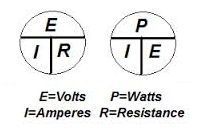
pier-chartsI am considering adding the charts shown at right to aid people in remembering what formulas to use when calculating the various parmaters. What do you think? Should I add them, or would that just muddy the waters?

The study guide will show the correct answers in bold. I don’t know what the deal is, but for some odd reason, the bold text doesn’t really show as bold here on the website.

Electrical principles, units, and terms: current and voltage; conductors and insulators; alternating and direct current; resistance; power

You don’t have to be an electronics engineer to get a Technician Class license, but it does help to know the basics of electricity and some of the units we use in electronics. The most important concepts are current, voltage, resistance, power, and frequency.

Voltage is the force that causes electrons to flow in a circuit. Voltage is sometimes called electromotive force, or EMF. Voltage is the electrical term for the electromotive force (EMF) that causes electron flow. (T5A05) The volt is the basic unit of electromotive force. (T5A11)

The letter V is shorthand for volts. About 12 volts is the amount of voltage that a mobile transceiver usually requires. (T5A06)

Current is the name for the flow of electrons in an electric circuit. (T5A03) Electrical current is measured in amperes. (T5A01) Direct current is the name for a current that flows only in one direction. (T5A04) Batteries supply direct current, or simply DC.

Alternating current is the name for a current that reverses direction on a regular basis. (T5A09) Frequency is the term that describes the number of times per second that an alternating current reverses direction. (T5A12) Alternating current, or AC, is what is available from your home’s wall sockets. Power supplies convert the AC into DC, which is required for most modern amateur radio equipment.

Resistance is the term used to describe opposition to current flow in a circuit. The basic unit of resistance is the ohm. The Greek letter omega (?) is shorthand for ohms.

Conductors are materials that conduct electrical current well, or, in other words, have a low resistance. The copper wires that we use to connect a power supply to a radio are good conductors because copper is a good electrical conductor. (T5A07)

Insulators are materials that that have a high resistance. They do not conduct electrical current very well. Plastics and glass, for example, are good electrical insulators. (T5A08)

The term that describes the rate at which electrical energy is used (or generated) is power. (T5A10) Electrical power is measured in watts. (T5A02)

Ohm’s Law: formulas and usage 

Hams obey Ohm’s Law!

Ohm’s Law is the relationship between voltage, current, and the resistance in a DC circuit. When you know any two of these values, you can calculate the third.

The most basic equation for Ohm’s Law is

E = I × R

In other words, when you know the current going into a circuit and the resistance of the circuit, the formula used to calculate voltage across the circuit is voltage (E) equals current (I) multiplied by resistance (R). (T5D02)

When you know the voltage across a circuit and the resistance of a circuit, the formula used to calculate resistance in a circuit is resistance (R) equals voltage (E) divided by current (I). (T5D03) We can also write this formula as

R = E / I

When you know the voltage across a circuit and the resistance of a circuit, the formula used to calculate current in the circuit is current (I) equals voltage (E) divided by resistance (R). (T5D01) This formula is written

I = E / R

Examples
The resistance of a circuit in which a current of 3 amperes flows through a resistor connected to 90 volts is 30 ohms. (T5D04)

R = E / I = 90 V / 3 A = 30 ?

The resistance in a circuit for which the applied voltage is 12 volts and the current flow is 1.5 amperes is 8 ohms.(T5D05)

R = E / I = 12 V / 1.5 A = 8 ?

The resistance of a circuit that draws 4 amperes from a 12-volt source is 3 ohms. (T5D06)

R = E / I = 12 V / 4 A = 3 ?

The current flow in a circuit with an applied voltage of 120 volts and a resistance of 80 ohms is 1.5 amperes. (T5D07)

I = E / R = 120 V / 80 ? = 1.5 A

The current flowing through a 100-ohm resistor connected across 200 volts is 2 amperes. (T5D08)

I = E / R = 200 V / 100 ? = 2 A

The current flowing through a 24-ohm resistor connected across 240 volts is 10 amperes. (T5D09)

I = E / R = 240 V / 24 ? = 10 A

The voltage across a 2-ohm resistor if a current of 0.5 amperes flows through it is 1 volt. (T5D10)

E = I × R = 0.5 A × 2 ? = 1 V

The voltage across a 10-ohm resistor if a current of 1 ampere flows through it is 10 volts. (T5D11)

E = I × R = 1 A × 10 ? = 10 V

The voltage across a 10-ohm resistor if a current of 2 amperes flows through it is 20 volts. (T5D12)

E = I × R = 2 A × 10 ? = 20 V

Filed Under: Electronics Theory

From my Twitter feed: learn electronics, visualize cellphones, NTS newsletter

December 11, 2013 By Dan KB6NU 3 Comments


imabug's avatarimabug @imabug
LearnAbout – Electronics learnabout-electronics.org/index.php


TheZerocool's avatarDenis S @TheZerocool
If your in the school of thought that mobile phone mast RF will cook your mind… check this out and begin to worry: goo.gl/XcrkAN


VA3QV's avatarBob Sharp @VA3QV
A link to a NTS Themed Newsletter : ve3gna.wordpress.com/2013/12/07/lat…

Filed Under: Electronics Theory, Public Service Tagged With: cell phones, electronics, traffic handling

Transforming impedances: Question G5C07

November 15, 2013 By Dan KB6NU 3 Comments

In the last two weeks, I’ve received e-mails from two readers of The No-Nonsense General-Class License Study Guide. Both questioned my explanation of how transformers transform impedance. I wrote:

Transformers are also used to transform impedances. The impedance ratio is also related to the turns ratio, but the transformation is equal to the square of the turns ratio. The turns ratio of a transformer used to match an audio amplifier having a 600-ohm output impedance to a speaker having a 4-ohm impedance is 12.2 to 1. (G5C07)

Doug wrote, “The only way I can reproduce the calculation is by taking the square root of the turns ratio.” His comment made me see where my explanation could be a bit misleading. I wrote back:

Think about it this way. An impedance transformation can go either way. When transforming from a higher impedance to a lower impedance, you divide by the square root of the turns ratio. When transforming a lower impedance to a higher impedance, you multiply by the square of the turns ratio. In either case, the impedance ratio is “related” to the square of the turns ratio.

I love getting feedback from my readers. Feedback like this helps me improve my study guides. If you have used one of my study guides, and have a comment or question about any of the material, please feel free to contact me.

Filed Under: Classes/Testing/Licensing, Electronic Components, Electronics Theory Tagged With: transformer

From my Twitter feed: dB, SW, SSTV

October 29, 2013 By Dan KB6NU Leave a Comment

EDNcom's avatarEDN.com @EDNcom
Engineers refer to measurements in dB all the time. Here’s a refresher on decibel basics. edn.com/design/test-an…


ke9v's avatar

Jeff Davis @ke9v
Radio World: Shortwave Efficacy to Be Pondered at BBG radioworld.com/article/shortw…


AMSAT_UK's avatar

AMSAT-UK @AMSAT_UK
ISS Amateur Radio Slow Scan TV Active wp.me/p2Mn4x-4Yk #amsat #hamr #iss #sstv

Filed Under: Electronics Theory, SSTV, SWLing

  • « Go to Previous Page
  • Page 1
  • Interim pages omitted …
  • Page 6
  • Page 7
  • Page 8
  • Page 9
  • Page 10
  • Interim pages omitted …
  • Page 13
  • Go to Next Page »

Primary Sidebar

No Nonsense Technician Class License Study Guide (for tests given between July 2026 and June 2030)

New No Nonsense Technican Class Study Guide now available!

The 2026 version of my Tech Class study guide is now available, and as always, the PDF version is FREE!. The ePub version costs $11.97, and a Kindle version and paperback version will be available on Amazon shortly.

Click here to get all of my "No Nonsense" study guides.

Also available: The CW Geek's Guide to Having Fun with Morse Code

W5SWL.Com
Retevis Ailunce H1 DMR Radio
DXpander: Cobweb antennas, Laser Cutting

You’ve got mail!

Enter your email address below and get an email every time I publish a new post.

Email


I frequently teach classes to help newcomers get their licenses. The next class will take place on Saturday, February 7, 2026 on the University of Michigan campus. Click here for more information.

If you can't make the class, subscribe to the mailing list to be notified of when the next class will be held.

You can always download my free study guide, and if you have any questions about the classes, or amateur radio in general, please feel free to email me directly.

Support KB6NU.Com

Donate $7.30 and get two of these cool stickers. Measuring 4.25-in. W by 2.75-in. H, it's perfect for your car, your shack, or wherever!

Contact me

If you have a question or comment about one of my blog posts, or a question about any of the material in my study guides, or just a question about ham radio in general, you can email me at [email protected].

Blogs You Should Also Read

  • AE5X: A CW-centric blog from Kingswood, Texas
  • K0LWC Blog
  • LA3ZA Ham Radio Blog
  • Little Radios, Big Fun – WB3GCK
  • Mr. Vacuum Tube's Blog
  • Radio Artisan – K3NG
  • The K0NR Weblog
  • VE3WDM's QRP Ham Radio Blog
  • W2LJ’s Blog

Ham Radio Websites

  • Dashtoons – The Hammin' Comedy by Jeff K1NSS

Podcasts

  • ICQ Podcast
  • Linux in the Ham Schack
  • No Nonsense Amateur Radio Podcast
  • Resonant Frequency Amateur Radio Podcast

Recent Comments

  • Michael Burkhardt on One lump or two (or three)?
  • Eric on POTA notes, 7/27/26
  • Steve KB3JC on How to “ragchew” on CW
  • Dan KB6NU on Yaesu FT-710: What’s the big deal?
  • Andrei on Yaesu FT-710: What’s the big deal?

Meta

  • Log in
  • Entries feed
  • Comments feed
  • WordPress.org

Footer

Copyright © 2026 Daniel M. Romanchik, KB6NU · Log in