
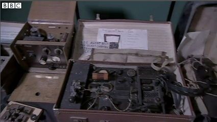
The unassuming Buckinghamshire village of Whaddon was the center of radio communications for the British in WW II. This BBC video celebrates the role that Whaddon played in helping the Allies win the war.
 Strange Beacons @StrangeBeacons
Links to a Large Collection of Online WebSDR Radios: websdr.org #SoftwareDefinedRadio #shortwave pic.twitter.com/7kR95VWbKb
 Alina Selyukh @alinaselyukh
 I’ve started teaching some basic electronics classes at the Ann Arbor District Library. They recently setup a makerspace they’re calling The Secret Lab and hired a guy named Steve Teeri to run it. I got hooked up with Steve after I inquired about the possibility of teaching some basic electronics classes. As it turned out, they had recently gotten to the point where they could start doing things like electronics classes in the Secret Lab so my inquiry had come at a fortuitous moment. I’ve since become the de-facto electronics/ham radio consultant to the library.
The first class we held was on how to use a digital multimeter. Five people showed up, and it turned into a class on circuits as much as a class on how to use a DMM. Overall, it went pretty well, and we followed that up with a class on how to use an oscilloscope.
This evening, we held a class on basic transistor circuits. This evening, we had nine people show up. There were a couple of older guys, three younger guys, two women, one who brought her two kids. The kids were eight and ten.
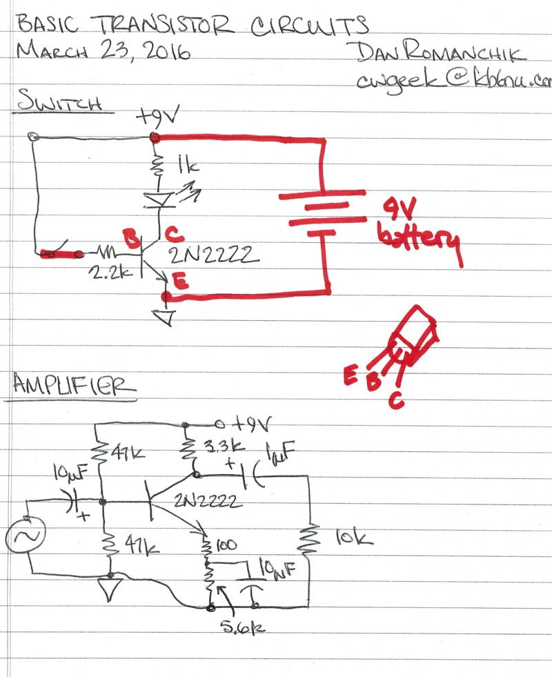
Initially, I had planned to have the students breadboard two circuits – a simple switch circuit and a common-emitter amplifier circuit. Both of these circuits can be found on the sheet below.
I figured that we’d be able to blow through the switch circuit, then dig into the amplifier circuit. WRONG! It took us nearly the entire class for everyone to get the switch circuit to work.
Some of it was my fault. First of all my schematic was lacking. It was a schematic that I got off the Internet, and while it was correct, it wasn’t detailed enough. As you can see from the red ink above, there were several omissions and errors:
An added complication was that the resistors that the library had purchased had blue bodies and very thin color bands. The result was that it was really difficult to really read the color code. At first, I thought it was just me and my failing eyesight, but I was relieved when one of the students had the same complaint. We actually had to dig out the multimeters and measure the resistors to make sure that we had the right ones.
Another reason that it took us so long is that I had to teach the students some really basic stuff, even before we got to the point where they could put the circuits together. This included the resistor color code and how to use the proto boards that we were using. This was certainly OK, but I hadn’t anticipated having to do that.
After about 45 minutes, all of the circuits were built, and the LEDs were lit. I asked them to disconnect the 2.2 k resistor to demonstrate how removing the base current turns off the transistor, and I think they all got that idea. I also explained how in practice that 2.2 k resistor wouldn’t be connected directly to a power supply but to perhaps an Arduino’s digital output. I also mentioned that instead of just turning an LED on and off, we might use the transistor to do some real work like switch a relay on and off. I think they got those ideas, too.
One guy asked how much current that the 2N2222 could switch. I had brought along with me a 2N2222 data sheet, and we looked up the maximum collector current for a 2N2222 (1.0 A). We then discussed how running the transistor at its maximum current rating might not be a good idea.
There was just enough time to go over the amplifier circuit quickly. Fortunately, I had the foresight to bring my own protoboard with the amplifier circuit already assembled on it. I quickly hooked up the scope probes, the signal generator, and the 9 V battery, and demonstrated how the circuit turned a 100 mV signal into a 2 V signal. For those who were interested, I was also able to talk a little bit about biasing.
So, the first thing that I take away from this experience is that I really need to gear down the level of the presentations. Second, I need to be a little more explicit with my instructions to students.
I’m hoping to do a lot more with the Ann Arbor District Library. I think that perhaps the next class will be an Arduino Basics class. At some point, too, I’ll want to reprise my DMM and oscilloscope class. I really love it that the library is giving me the opportunity to do this.
NOTE! On July 1, 2020, this post will become obsolete as the 2020 Extra Class question pool goes into effect. Please refer to the post from the 2020 No Nonsense Extra Class Study Guide instead.
E4E – Noise suppression: system noise; electrical appliance noise; line noise; locating noise sources; DSP noise reduction; noise blankers; grounding for signals
Noise is often a real problem for radio amateurs. Fortunately, by understanding how noise is generated and how to reduce or eliminate it, noise can be tamed.
Atmospheric noise is naturally-occurring noise. Thunderstorms are a major cause of atmospheric static. (E4E06) There’s not much you can do to eliminate, but you can often use a receiver’s noise blanker to help you copy signals better. Signals which appear across a wide bandwidth (like atmospheric noise) are the types of signals that a receiver noise blanker might be able to remove from desired signals. (E4E03) Ignition noise is one type of receiver noise that can often be reduced by use of a receiver noise blanker. (E4E01)
One undesirable effect that can occur when using an IF noise blanker is that nearby signals may appear to be excessively wide even if they meet emission standards. (E4E09)
Many modern receivers now use digital signal processing (DSP) filters to eliminate noise. All of these choices are correct when talking about types of receiver noise can often be reduced with a DSP noise filter (E4E02):
One disadvantage of using some types of automatic DSP notch-filters when attempting to copy CW signals is that the DSP filter can remove the desired signal at the same time as it removes interfering signals. (E4E12)
While filters can be very effective at reducing noise, it is often better to figure out what is generating the noise and taking steps to reduce or eliminate the amount of noise generated in the first place. For example, one way you can determine if line noise interference is being generated within your home is by turning off the AC power line main circuit breaker and listening on a battery operated radio. (E4E07) If by doing this you determine that an electric motor is a problem, noise from an electric motor can be suppressed by installing a brute-force AC-line filter in series with the motor leads. (E4E05)
All of these choices are correct when it comes to the cause of a loud roaring or buzzing AC line interference that comes and goes at intervals (E4E13):
Sometimes your own equipment may be the cause of received noise. Cables in an amateur radio station, for example, can radiate or pick up interference. Common mode currents are the culprits. Common mode currents on the shield and conductors can cause shielded cables to radiate or receive interference. (E4E15) To eliminate this interference, make sure to ground the shield at one end of the cable. Common-mode current flows equally on all conductors of an unshielded multi-conductor cable. (E4E16)
Electrical wiring may also pick up interference. A common-mode signal at the frequency of the radio transmitter is sometimes picked up by electrical wiring near a radio antenna. (E4E08)
The main source of noise in an automobile is the alternator. Conducted and radiated noise caused by an automobile alternator be suppressed by connecting the radio’s power leads directly to the battery and by installing coaxial capacitors in line with the alternator leads. (E4E04)
Personal computer and other digital devices can also generate noise. One type of electrical interference that might be caused by the operation of a nearby personal computer is the appearance of unstable modulated or unmodulated signals at specific frequencies. (E4E14) All of these choices are correct when talking about common characteristics of interference caused by a touch controlled electrical device: (E4E10)
Noise can even be generated by the most unlikely things. For example, it is mostly likely that nearby corroded metal joints are mixing and re-radiating the broadcast signals if you are hearing combinations of local AM broadcast signals within one or more of the MF or HF ham bands. (E4E11)
This is a press release that I recently received from the National Institute of Standards and Technology (NIST). Communications has always relied on the precise measurement of time. Today, JT65 is one mode that relies on accurate time synchronization. That’s why it’s important to know something about time, and how we keep on time today….Dan
 The Internet Time Service operated by the National Institute of Standards and Technology (NIST) serves much of the Earth, with customers from around the globe. In one month of study alone, just two of the 20 NIST servers that supply time information to Internet-connected devices received requests from 316 million unique Internet Protocol (IP) addresses, according to detailed data about the service published for the first time. This represents at least 8.5 percent of devices on the entire Internet.
“NIST should be very proud of the Internet Time Service, which is an important public resource,” says NIST physicist Jeff Sherman, who collected the statistics and co-authored the new report. (The study focused on just two servers because they are local to NIST and easy to access, and they carry 25 percent of the total traffic, a statistically representative sample.)
NIST has operated the Internet Time Service since 1993. The service receives about 16 billion requests per day (as of January 2016). The 20 timeservers are located at 12 sites around the country, including NIST campuses in Gaithersburg, Md., and Boulder, Colo. The servers are linked to the NIST time scale, an ensemble of atomic clocks that maintain the U.S. version of Coordinated Universal Time. The time scale is calibrated by the NIST-F1 and NIST-F2 cesium fountain atomic clocks, the U.S. civilian time standards.
Importantly, the Internet Time Service provides a reliable source of time independent of the satellite-based Global Positioning System. Demand may increase with the growth of the Internet of Things, in which more devices will be connected to the Internet without any direct human intervention.
NIST Fellow Judah Levine came up with the original idea of distributing time over the Internet and wrote most of the software. The service is just one of the ways NIST distributes time-of-day information. Other methods include NIST radio stations, telephone call-in services, and the website http://time.gov.
E8B – Modulation and demodulation: modulation methods; modulation index and deviation ratio; frequency and time division multiplexing; Orthogonal Frequency Division Multiplexing
In FM modulation, the two primary parameters of interest are deviation ratio and modulation index. Deviation ratio is the ratio of the maximum carrier frequency deviation to the highest audio modulating frequency. (E8B09) The deviation ratio of an FM-phone signal having a maximum frequency swing of plus-or-minus 5 kHz when the maximum modulation frequency is 3 kHz is 1.67. (E8B05)The deviation ratio of an FM-phone signal having a maximum frequency swing of plus or minus 7.5 kHz when the maximum modulation frequency is 3.5 kHz is 2.14. (E8B06)
The term for the ratio between the frequency deviation of an RF carrier wave, and the modulating frequency of its corresponding FM-phone signal is modulation index. (E8B01) The modulation index is equal to the ratio of the frequency deviation to the modulating frequency. The modulation index of a phase-modulated emission does not depend on the RF carrier frequency. (E8B02)
The modulation index of an FM-phone signal having a maximum frequency deviation of 3000 Hz either side of the carrier frequency, when the modulating frequency is 1000 Hz is 3. (E8B03) The modulation index of an FM-phone signal having a maximum carrier deviation of plus or minus 6 kHz when modulated with a 2-kHz modulating frequency is 3. (E8B04)
Some communications systems use multiplexing techniques to to combine several separate analog information streams into a single analog radio frequency signal. When a system uses frequency division multiplexing, two or more information streams are merged into a “baseband,” which then modulates the transmitter. (E8B10). When a system uses digital time division multiplexing, two or more signals are arranged to share discrete time slots of a data transmission. (E8B11)
Orthogonal Frequency Division Multiplexing is a digital modulation technique using subcarriers at frequencies chosen to avoid intersymbol interference. (E8B08) Orthogonal Frequency Division Multiplexing is a technique used for high speed digital modes. (E8B07)
On July 1, 2020, this post will be obsolete. See the corresponding post from my 2020 version of No Nonsense Extra Class License Study Guide.
E7H – Oscillators and signal sources: types of oscillators; synthesizers and phase-locked loops; direct digital synthesizers; stabilizing thermal drift; microphonics; high accuracy oscillators
Oscillator circuits are one of the basic building blocks of amateur radio equipment. Oscillator circuits are not only used to generate the signals we transmit. They are also an integral part of receivers, such as the superheterodyne receiver.
You can think of an oscillator as an amplifier with a tuned circuit at the input. This tuned circuit might be an LC circuit or a crystal. The values of the components in the tuned circuit determine the output frequency of the oscillator. There are three types of oscillator circuits commonly used in Amateur Radio equipment – Colpitts, Hartley and Pierce. (E7H01) Colpitts and Hartley oscillator circuits are commonly used in VFOs. (E7H06)
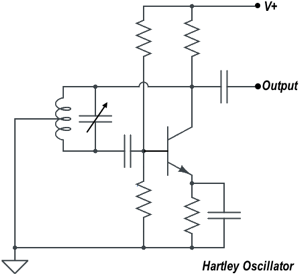
For a circuit to oscillate, it must have positive feedback. In a Hartley oscillator (shown in the figure below), positive feedback is supplied through a tapped coil. (E7H03)
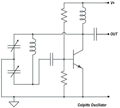
In a Colpitts oscillator, positive feedback is supplied through a capacitive divider. (E7H04)
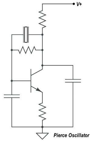
In a Pierce oscillator, positive feedback is supplied through a quartz crystal. (E7H05) To ensure that a crystal oscillator provides the frequency specified by the crystal manufacturer, you must provide the crystal with a specified parallel capacitance. (E7H12) NPO capacitors are components that can be used to reduce thermal drift in crystal oscillators. (E7H08)
One problem that oscillators sometimes have is called microphonics. Changes in oscillator frequency due to mechanical vibration describes a microphonic. (E7H02) An oscillator’s microphonic responses can be reduced by mechanically isolating the oscillator from its enclosure. (EH707)
Digital frequency synthesizers
Most modern amateur radio transceivers use digital frequency synthesizers instead of analog oscillators to generate RF signals. One reason for this is that they are much more stable than analog oscillators. The two main types of digital frequency synthesizers are the direct digital synthesizer and the phase-locked loop synthesizer.
A direct digital synthesizer is the type of frequency synthesizer circuit that uses a phase accumulator, lookup table, digital to analog converter and a low-pass anti-alias filter. (E7H09) The information contained in the lookup table of a direct digital frequency synthesizer is the amplitude values that represent a sine-wave output. (E7H10)
Another type of frequency synthesizer that’s popular are those that use a phase-locked loop. A phase-locked loop circuit is an electronic servo loop consisting of a phase detector, a low-pass filter, a voltage-controlled oscillator, and a stable reference oscillator. (E7H14) Frequency synthesis, FM demodulation are two functions that can be performed by a phase-locked loop. (E7H15)
Both direct digital synthesizers and phase-locked loop synthesizers have issues with spectral purity. The major spectral impurity components of direct digital synthesizers are spurious signals at discrete frequencies. (E7H11)
Because frequency multipliers are often used for generating RF signals at microwave frequencies, it is very important that the oscillators used in microwave transmitters are accurate and stable. Any inaccuracy or instability will be multiplied along with the desired frequency. All of these choices are correct when talking about techniques for providing highly accurate and stable oscillators needed for microwave transmission and reception: (E7H13)
On July 1, 2020, this post will be obsolete. See the corresponding post from my 2020 version of No Nonsense Extra Class License Study Guide.
This section is almost entirely new. I’m far from being an expert on digital signal processing (DSP) and software-defined radio (SDR), so if you have some expertise in these areas, please feel free to comment on this section….Dan
Some modern radios modulate and demodulate signals entirely in software. This type of radio is called a software-defined radio, or SDR. One type of SDR uses a process called direct digital conversion to convert the analog radio signal into a series of numbers. As applied to software defined radios, direct digital conversion means incoming RF is digitized by an analog-to-digital converter without being mixed with a local oscillator signal. (E7F01)
Analog-to-digital converter specifications are crucial for a software-defined radio. For example, sample rate is the aspect of receiver analog-to-digital conversion that determines the maximum receive bandwidth of a Direct Digital Conversion SDR. (E7F10) An analog signal must be sampled at twice the rate of the highest frequency component of the signal by an analog-to-digital converter so that the signal can be accurately reproduced. (E7F05)
Voltage resolution is also important. The reference voltage level and sample width in bits sets the minimum detectable signal level for an SDR in the absence of atmospheric or thermal noise. (E7F11) The minimum number of bits required for an analog-to-digital converter to sample a signal with a range of 1 volt at a resolution of 1 millivolt is 10 bits. (E7F06)
Modern software defined radios convert an incoming signal into two data streams: I and Q. The letters I and Q in I/Q modulation (and demodulation) represent In-phase and Quadrature. (E7F17). The I and Q data streams are 90 degrees out of phase with one another, and as a result, the two data streams not only show how the amplitude of a signal is changing, but how the phase of a signal is changing.
The digital process that is applied to I and Q signals in order to recover the baseband modulation information is the Fast Fourier Transform. (E7F12) Converting digital signals from the time domain to the frequency domain is the function that a Fast Fourier Transform performs. (E7F07)
Once a signal has been digitized, or converted into a series of numbers, it can be digitally filtered. The kind of digital signal processing audio filter used to remove unwanted noise from a received SSB signal is an adaptive filter. (E7F02) Another type of digital filter, one that is often used in a direct digital conversion receiver, is the finite impulse, or FIR, filter. An advantage of a Finite Impulse Response (FIR) filter vs an Infinite Impulse Response (IIR) digital filter is that FIR filters delay all frequency components of the signal by the same amount. (E7F15)
The FIR filter in a software defined radio might also be a decimating filter. The decimation function reduces the effective sample rate by removing samples when using a digital filter. (E7F08) SDRs perform decimation because the signal of interest will usually have a significantly lower bandwidth than the digitized signal, and reducing the sample rate allows SDRs to use less-powerful processors. One way the sampling rate of an existing digital signal might be adjusted by a factor of 3/4 is to interpolate by a factor of three, then decimate by a factor of four. (E7F16)
An anti-aliasing digital filter is required in a digital decimator because it removes high-frequency signal components which would otherwise be reproduced as lower frequency components. (E7F09)
Taps in a digital signal processing filter provide incremental signal delays for filter algorithms. (E7F13) More taps would allow a digital signal processing filter to create a sharper filter response. (E7F14)
Signals can also be generated using SDR techniques. A common method of generating an SSB signal using digital signal processing is to combine signals with a quadrature phase relationship. (E7F04) The type of digital signal processing filter used to generate an SSB signal is a Hilbert-transform filter. (E7F03)
On July 1, 2020, this post will be obsolete. See the corresponding post from my 2020 version of No Nonsense Extra Class License Study Guide.
The questions on digital signal processing (DSP) and software defined radio (SDR) were removed from this section, and E7F, which does have questions on these two topics……Dan
E7E – Modulation and demodulation: reactance, phase and balanced modulators; detectors; mixer stages
Modulation is the process of adding some kind of information, including voice and digital information, to a carrier signal. The most common types of modulation that we use in amateur radio are amplitude modulation (AM) and frequency modulation (FM). Single-sideband, or SSB, is a form of amplitude modulation.
To frequency modulate a carrier, a transmitter will sometimes use a modulator that varies the phase of the signal. This is sometimes called phase modulation (PM). One way to generate FM phone emissions is to use a reactance modulator on the oscillator. (E7E01) The function of a reactance modulator is to produce PM signals by using an electrically variable inductance or capacitance. (E7E02) An analog phase modulator functions by varying the tuning of an amplifier tank circuit to produce PM signals. (E7E03)
To boost the higher audio frequencies, a pre-emphasis network is often added to an FM transmitter. (E7E05) For compatibility with transmitters using phase modulation, de-emphasis is commonly used in FM communications receivers. (E7E06)
Amplitude modulation and single-sideband signals are produced using mixer circuits. The carrier frequency and the baseband signals are input to the mixer circuit which produces an amplitude modulated output. The term baseband in radio communications refers to the frequency components present in the modulating signal. (E7E07) The principal frequencies that appear at the output of a mixer circuit are the two input frequencies along with their sum and difference frequencies. (E7E08)
When using a mixer, you must take care not to use too high of a signal at the inputs. Spurious mixer products are generated when an excessive amount of signal energy reaches a mixer circuit. (E7E09)
Single sideband is most often used for phone transmission on the HF bands and for weak-signal operation on the VHF and UHF bands. One way a single-sideband phone signal can be generated is by using a balanced modulator followed by a filter. (E7E04) A balanced modulator is a type of mixer. The output of a balanced modulator, however, does not contain the carrier frequency, only the two sidebands.
At the receiving station, a modulated signal has to be demodulated. Amplitude modulated signals are often demodulated using a diode detector circuit. A diode detector functions by rectification and filtering of RF signals. (E7E10)
For demodulating SSB signals, you want something a little more sophisticated. A product detector is a type of detector that is well suited for demodulating SSB signals. (E7E11) A product detector is actually a frequency mixer. It takes the product of the modulated signal and a local oscillator, hence the name. In an FM receiver, the circuit for detecting FM signals is a frequency discriminator. (E7E12)
On July 1, 2020, this post will be obsolete. See the corresponding post from my 2020 version of No Nonsense Extra Class License Study Guide.
E7C – Filters and matching networks: types of networks; types of filters; filter applications; filter characteristics; impedance matching; DSP filtering
Because the impedance of inductors and capacitors vary with frequency, we often make filters out of them. One of the most common is the T-network filter, so called because it looks like the letter T. An example is shown in figure E7C-1.
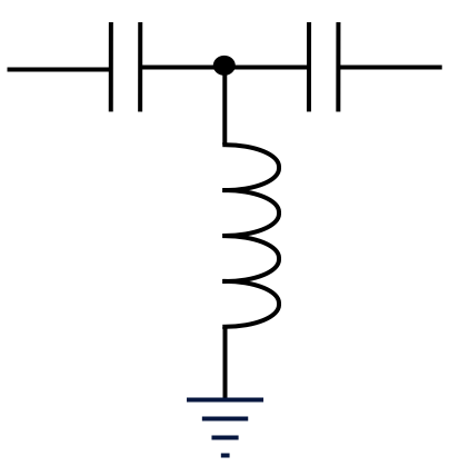
This particular filter has the characteristic of being a high-pass filter. That is to say it will pass frequencies above a certain frequency, called the cutoff frequency, and block frequencies below that frequency. A T-network with series capacitors and a parallel shunt inductor has the property of it being a high-pass filter. (E7C02) The reason the circuit acts this way is that as the frequency of a signal increases, capacitive reactance decreases and inductive reactance increases, meaning that lower-frequency signals are more likely to be shunted to ground.
A circuit containing capacitors and inductors can also form a low-pass filter. A low-pass filter is a circuit that passes frequencies below the cutoff frequency and blocks frequencies above it.
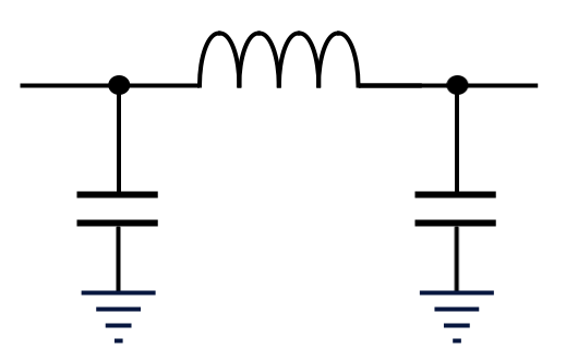
Pi is the common name for a filter network which is equivalent to two L networks connected back-to-back with the inductors in series and the capacitors in shunt at the input and output. (E7C11). The circuit shown in figure E7C-2 is called a pi filter because it looks like the Greek letter π.
The capacitors and inductors of a low-pass filter Pi-network are arranged such that a capacitor is connected between the input and ground, another capacitor is connected between the output and ground, and an inductor is connected between input and output. (E7C01) The reason the circuit acts this way is that as the frequency of a signal increases, capacitive reactance decreases and inductive reactance increases, meaning that higher-frequency signals are more likely to be shunted to ground.
Pi networks can also be used to match the output impedance of one circuit to the input impedance of another or the output impedance of a transmitter to the input impedance of an antenna. An impedance-matching circuit transforms a complex impedance to a resistive impedance because it cancels the reactive part of the impedance and changes the resistive part to a desired value. (E7C04) One advantage of a Pi matching network over an L matching network consisting of a single inductor and a single capacitor is that the Q of Pi networks can be varied depending on the component values chosen. (E7C13)
A Pi network with an additional series inductor on the output describes a Pi-L network used for matching a vacuum-tube final amplifier to a 50-ohm unbalanced output. (E7C12) One advantage a Pi-L-network has over a Pi-network for impedance matching between the final amplifier of a vacuum-tube transmitter and an antenna is that it has greater harmonic suppression. (E7C03)
Piezoelectric crystals are also used to build filters. A crystal lattice filter is a filter with narrow bandwidth and steep skirts made using quartz crystals. (E7C15) The relative frequencies of the individual crystals is the factor that has the greatest effect in helping determine the bandwidth and response shape of a crystal ladder filter. (E7C08) A “Jones filter” is a variable bandwidth crystal lattice filter used as part of a HF receiver IF stage. (E7C09)
Different types of filters have different characteristics. For example, a Chebyshev filter is a filter type described as having ripple in the passband and a sharp cutoff. (E7C05) On the other hand, the distinguishing features of an elliptical filter are extremely sharp cutoff with one or more notches in the stop band. (E7C06)
Filters have both amplitude and phase-response characteristics. In some applications, both are important. Digital modes, for example, are most affected by non-linear phase response in a receiver IF filter. (E7C14)
Often, you’ll choose a filter type for a particular application. For example, to attenuate an interfering carrier signal while receiving an SSB transmission, you would use a notch filter. (E7C07) A cavity filter would be the best choice for use in a 2 meter repeater duplexer. (E7C10)
Today, many of these filters are implemented using digital signal processing. The kind of digital signal processing audio filter might be used to remove unwanted noise from a received SSB signal is an adaptive filter. (E7C08) The type of digital signal processing filter might be used to generate an SSB signal is a Hilbert-transform filter. (E7C09)
