• Skip to primary navigation
  • Skip to main content
  • Skip to primary sidebar
  • Skip to footer

KB6NU's Ham Radio Blog

KB6NU's Ham Radio Blog
  • HOME
  • Study Guides
  • Teach a One-Day Tech Class
  • W8SRC Repeater Guide
  • Advertise
  • Hire Me

Electronics Theory

For All Times, For All Peoples: How Replacing the Kilogram Empowers Industry

November 28, 2018 By Dan KB6NU 2 Comments

If this looks more polished than my usual blog posts, that’s because it is! I took this directly from the National Institute of Standards and Technology (NIST) website. Because it’s a publication of the federal government, it’s in the public domain. They do a much better job explaining this than I do.

What does the kilogram have to do with electronics? Well, not only did the scientists redefine the kilogram, but they also redefined the amp, volt, and ohm…..Dan


November 27, 2018
By Jim Olthoff
Credit: BIPM/NIST

Two unusual things happened on Nov. 16, 2018. Fifty-five nations from every continent (except Antarctica) agreed on something, and metrology, the science of measurement, was major news!

On that day in Versailles, France, the world’s measurement experts voted to do something momentous. They passed a resolution that specifies the exact values for seven fundamental constants of physics and, in the process, they made it possible for anyone, anywhere to make precise, accurate measurements using the International System of Units (SI), popularly known as the metric system.

You may have seen some of the articles with titles like: “The Kilogram is Dead. Long Live the Kilogram!”

But wait, you may be thinking, can’t we already make precise, accurate measurements everywhere?

As often is the case in science, the answer is, “It depends.” Yes, most industrialized nations can make extremely accurate measurements in support of industry and science, but reliance on a single platinum-iridium kilogram artifact in France has been inconvenient and has started to constrain what can be achieved at the tiny masses now used in advanced pharmaceutical design and in other advanced manufacturing areas.

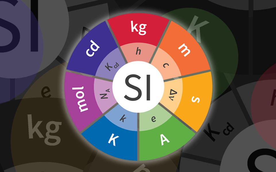
After decades of groundbreaking laboratory work, the world’s scientific and technical community came together on November 16, 2018, to redefine four of the seven base units for the International System of Units (SI).

The resolution passed in Versailles now defines the kilogram not as a single artifact but in terms of the fundamental constant referred to as the Planck constant. Using the fixed value of the Planck constant, mass can be realized at any magnitude by equating the electromagnetic force it takes to hold a mass against the force of gravity. With that quantity in hand, the kilogram has been freed from its platinum-iridium shackles. From now on, comparisons of a country’s copy of the kilogram with the French prototype will no longer be necessary. Any nation, any industry that needs to measure mass with world-class accuracy need only build something called a Kibble balance.

Named for its inventor Bryan Kibble, this is a measurement instrument that has been improved over 30 years by NIST, the National Research Council of Canada, the National Physical Laboratory in the U.K., and other nations. It takes advantage of fundamental relationships between mass and energy at the atomic level, immortalized by Einstein’s famous equation, E=mc2  (energy=mass times the speed of light squared). With the now fixed, extremely accurate value for the Planck constant, a number that relates a photon’s energy to its frequency, anyone, anywhere can make a Kibble balance with the accuracy they need for mass measurements without needing calibrations from NIST or any other national measurement institute. This is possible because the readout from a Kibble balance is provided by nature through unchanging laws of physics, not a fragile object made by humans.

The watt balance lets researchers determine the mass of an object indirectly via two measuring modes that determine two different quatities: the strength of the magnetic field, and the current running through a coil of wire. Credit: Sean Kelley/NIST

So, what does this momentous change in measurement mean to you? When you buy your deli meat by the pound or the kilogram, will you get a better deal? No, consumers will not notice any change, and that’s the idea. An accurate and well-functioning measurement infrastructure is one you don’t notice. It’s only when things start to go wrong that you notice it, which is how we got here in the first place.

Although the kilogram is getting the most dramatic facelift, the ampere, kelvin and mole are also getting new, or slightly edited definitions as well.

The ampere

In fact, the redefinition of the ampere will have the most immediate effect. Previously, the ampere was defined as: “The ampere is that constant current which, if maintained in two straight parallel conductors of infinite length, of negligible circular cross-section, and placed 1 meter apart in vacuum, would produce between these conductors a force equal to 2 x 10⁻⁷ newton per meter of length.”

I don’t know about you. But I’ve never seen a conductor of infinite length and negligible cross-section, and the only place to find a perfect vacuum is in space, which is inconvenient, to say the least.

The ampere is weird because it’s an electrical measure but is defined in terms of force. And because it’s so hard, actually impossible to realize the amp as defined, we have had to define it in terms of its relation to the ohm and the volt when it’s really the ampere that should define these units! And what’s worse is that the units that the ohm and the volt are defined by aren’t even among the SI units!

But now, all that has changed. The volt and ohm have been tied to natural constants h and e—the Planck constant, h, described above, and e, the innate charge of an electron, the value of which was also fixed as part of the Versailles resolution.

To be exact, and there’s no better way to be, the ampere’s new definition is:

“The ampere, symbol A, is the unit of electric current. Its magnitude is set by fixing the numerical value of the elementary charge to be equal to exactly 1.602176634 x 10⁻¹⁹ when it is expressed in the SI unit sA [ampere seconds], which is equal to C.”

What all that means in terms that are easier to grasp is that the ampere is now (practically) defined as 6.241 x 10¹⁸ electrons, or 1 coulomb’s (C) worth, moving past a point per second.

Realizing that definition fully in a practical manner still presents a formidable technological challenge, but we can measure it precisely enough at this point for companies that manufacture electrical meters and devices like that to “feel” it and be able to adjust their instruments accordingly.

Eventually, we will build the “quantum ampere,” a chip-scale device that will produce exactly a known quantity of current by actually counting electrons. We’re not there yet, but developing “NIST on a Chip” technologies, working standards that never need calibration, is a focus area for us over the coming years.
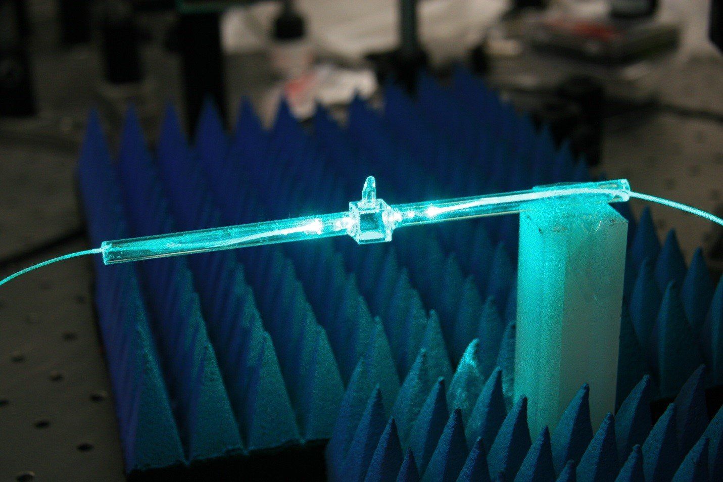
NIST researchers are working to create a fundamentally new technology for measuring electromagnetic fields based on atomic-vapor measurements of the sort now used for time, frequency, and length metrology. Directly traceable to the SI, self-calibrating, and capable of absolute measurements on a small spatial scale (i.e., subwavelength) in both the far-field and near-field, the system will have far-reaching applications, including NIST-on-a-Chip transferable E-field standards, new biomedical metrology, new imaging capability, and traceable calibrations above 110 GHz (currently not available).
Credit: Curt Suplee/NIST

NIST used to make a considerable amount of money doing calibrations. That amount has gone down over time as the number of devices coming to NIST for calibration has gone down. This may surprise you, but I’d like to see that trend continue. Why? Because we want to put world-class measurement technologies directly in the hands of industry. NIST changed its name from the National Bureau of Standards back in 1988, but it’s only now that we’ve really started to make the “technology” in the “National Institute of Standards and Technology” transition. Just like we’re looking to do with the Kibble balance, the more we can enable and empower industry, the less they HAVE to come to us, the more time and money they can spend putting our technologies to work to develop new products, and the more time we can spend working with them to solve more pressing measurement issues.

The kelvin

The kelvin (K), the SI unit of temperature, is presently defined as “1/273.16 of the thermodynamic temperature of the triple point of water.” Water’s triple point is observed by using a sealed glass vessel that contains water in gaseous, liquid and solid forms simultaneously. When water is in that state and under a specified amount of pressure, it is exactly 273.16 K (though that depends on getting just the right mix of water molecules, something that is hard to do from place to place). Water currently provides the ultimate anchor point for realizing temperature and calibrating thermometers, but there are also many other substances that we use when doing calibrations. The thermometers we use are standard platinum resistance thermometers, which measure how the electrical resistance of platinum changes with temperature and are very fragile and expensive.

This approach is essentially the way that thermometers have been calibrated for more than 100 years. Doing so requires special facilities and expertise that wouldn’t make economic sense for the average company to maintain, so they come to us. But why go through all the hassle? Temperature is just the motion of particles, so why not measure that directly? That is, why not measure temperature at the quantum level?

A first step toward measuring temperature based on invariant quantum phenomena is redefining the kelvin in terms of the Boltzmann constant, which relates energy to temperature, in this case, 1.380649 x 10⁻²³ J K-1 (joules per kelvin). While platinum thermometers will continue to be used for the foreseeable future, there are several potential means of doing quantum, chip-based measurements, including Johnson noise thermometry and photonic thermometry. And we are working to develop those technologies so that industry can have access to highly accurate temperature sensors that never need calibrating and that can be put just about anywhere, such as chemical processing plants, energy plants and inhospitable environments.
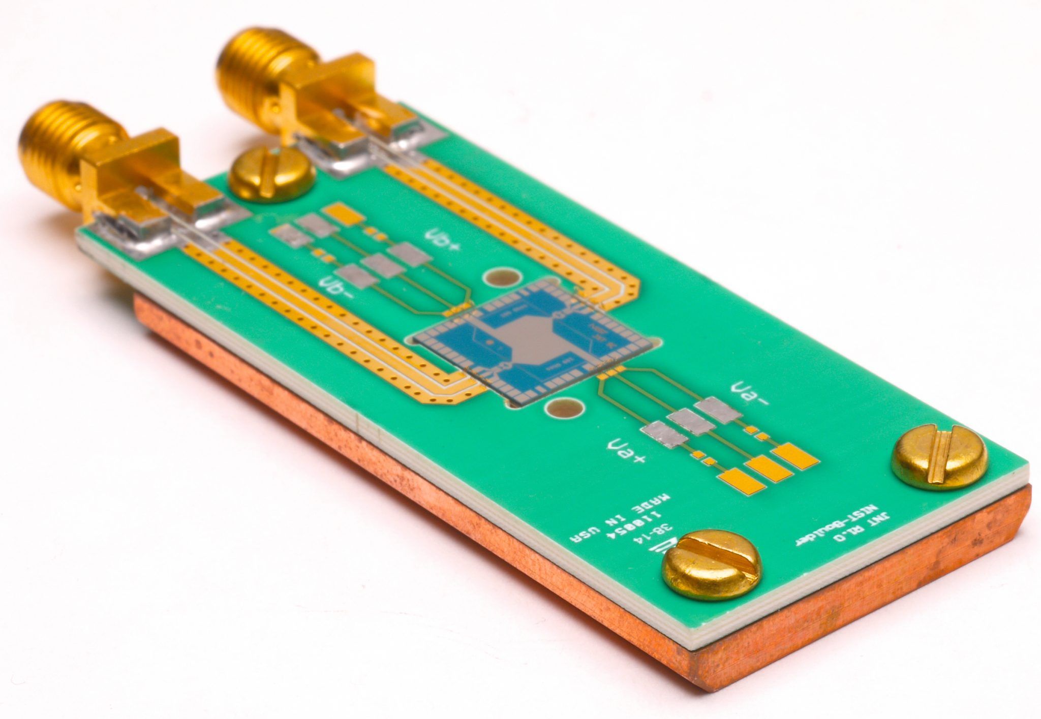
This quantum voltage noise source (QVNS) provides a fundamentally accurate voltage signal that can be compared to the voltage noise from electrons in a resistor. Measuring the voltage noise enabled researchers to determine the Boltzmann constant, which relates an energy of a system to its temperature.
Credit: Dan Schmidt/NIST

The mole, the SI unit of amount of substance will have its definition edited only slightly. The mole is really just a quantity of molecules or atoms that’s used to make chemical formulations a little easier and was defined as the number of entities in 12 grams of carbon-12, which is equal to the Avogadro number, 6.02214076×10²³, an enormous quantity. Now, the Avogadro number is simply and exactly defined.

We did it!

All these new definitions will make it easier for the units to be measured and will eventually make them accessible to everyone with the right equipment. This will be a great step forward for metrology, as it will put the power of accurate precision measurements, the kind that used to be realizable only at metrology institutes like NIST, directly in the hands of those who need them at a much lower cost. And we don’t plan to stop with the SI base units. I see our NIST-on-a-Chip project expanding to include measurements in all kinds of useful areas such as humidity, acceleration, radiation and more.

For instance, we have several companies looking to commercialize our process for measuring laser power. We want to bring companies in even earlier in the process, as soon as we realize that a measurement technology is transferable. We would work with those companies under cooperative agreements to not only manufacture the technology but to help develop it. We’re putting together a new commercialization roadmap to make sure that we are taking advantage of every opportunity to collaborate with our industry partners every step along the way to get these devices out of the lab and into the marketplace where they can do some good.

It’s taken a generation of metrologists to realize the potential of basing our fundamental measurement units on the fundamental constants of nature. The decision the world made on Nov. 16 is setting us down this new path. The seed we planted 40 years ago when we began the quest to redefine the kilogram has since grown, sprouted branches and bloomed. It’s an enormous achievement, and I’m extremely proud of the work my colleagues here at NIST and around the world have done. I’m humbled to have had a chance to play even a small role in something so momentous. But, as always, there’s still work to be done, and I’m looking forward to what lies ahead.

Delegates representing 60 countries at the 26th General Conference of Weights and Measures voted on an historic change to the International System of Units (SI).
Filed Under: Electronics Theory Tagged With: kilogram, SI

Diodes, Arduino, and VSWR: Articles from popular trade magazines

November 19, 2018 By Dan KB6NU Leave a Comment

4½ Practical Uses for a Diode

The ubiquitous diode—though you likely have a good understanding of this device, this primer of sorts acts as a quick-read guide, highlighting many of the essentials you need to know.
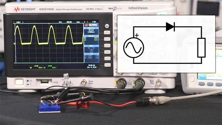
One of the functions of a diode is to rectify an AC signal.

Rapid Prototyping in the Era of Arduino, mikroBUS, and Processing

The age of rapid prototyping is upon us, with companies such as MikroElektronika, Adafruit, and Arduino making it easier for designers to bring concepts together in an impressively short period of time.


I got this by way of EE Journal:

Measure a Voltage Standing Wave Ratio (VSWR) to Quantify Transmission Line Imperfections

Impedance mismatches in a radio-frequency (RF) electrical transmission line cause power loss and reflected energy. Voltage standing wave ratio (VSWR) is a way to measure transmission line imperfections. This tutorial defines VSWR and explains how it is calculated. Finally, an antenna VSWR monitoring system is shown.

Filed Under: Antennas, Building/Homebrew, Electronics Theory, Microcontrollers Tagged With: Arduino, diodes, SWR

Open tabs: How does radio work?, digital ATV, telegraph kit

September 4, 2018 By Dan KB6NU 2 Comments

Sometimes, I’ll find something interesting on the internet, or in my email, and open up a tab in my web browser meaning to read the page or watch the video at some later date. Often, those tabs stay open for a week or more. Here are three such tabs that relate to amateur radio….Dan


How does radio really work?

N1SPY explains how radio receivers work and builds a radio receiver from scratch


Telegraph Decoder Kit

MAKE: magazine describes this kits as:

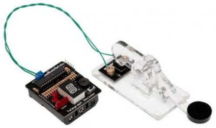
…a fun, educational way to learn Morse code and soldering. Some say the telegraph is a thing of the past, but Spikenzie Labs dusted off the design and brought it back to the present! This kit blends a nostalgic telegraph style keyer with an Arduino based decoder. As you successfully key in letters they are shown on a 16 segment alpha-numeric LED display. Two LEDs flash indicating ‘dots’ or ‘dashes’ and a piezo provides audio feedback for the telegraph. After a pause, the display flashes back the last set of characters received.

Since you can re-program the chip with the Arduino IDE, you can hack it for additional functionality (like hooking it up to a ham transceiver or sending automated messages.) Another well done, great looking kit by Spikenzie Labs!

It seems a little expensive ($45), but it is Arduino-based, so it is hackable. Might be fun to play around with.


Free ATV magazine

CQ-DATV is a free magazine for ATV enthusiasts. Despite the name, the magazine covers all aspects of amateur TV. The latest issue was just published and includes:


  • News and World Round-up
  • A look at Repeater Control Hardware and Software
  • DKARS advert
  • VIT Character generator
  • TV Amateur
  • VMIX Matrix 16 Way Keypad Controller
  • One from the Vault
  • 2018 Region 1 ATV Contest Results


Back issues are available all the way back to Issue #1, published in February 2013.


Filed Under: ATV, CW, Electronics Theory Tagged With: Arduino, atv, video

From Electronic Design: Common-emitter amplifiers, intro to capacitors, evaluate oscilloscopes

August 30, 2018 By Dan KB6NU Leave a Comment

Here are three articles from Electronic Design that you might find amusing. Electronic Design is a magazine for electronics engineers, but these articles have good information for amateur radio operators as well…..Dan


A Closer Look at the Common Emitter Amplifier and Emitter Follower.
Usually targeted at audio applications, these circuit blocks find homes in all types of designs. Here’s a quick study of their operation and properties.

I’m not sure why the author decided to use a 2N5550 instead of the more common 2N2222 for this article, but it’s a good explanation of how the common emitter amplifier works. If you’ve never breadboarded one, I’d suggest that you do so and play around with it.


Capacitor Basics and Their Uses in Power Applications.
Capacitors play key roles in the design of filters, amplifiers, power supplies and many additional circuits. Here’s a brief guide to the different types and the applications they’re best suited for.


How to Evaluate Oscilloscope Signal Integrity.
Oscilloscope signal integrity impacts signal shape and measurement values. This article is intended to help you assess the signal integrity of your oscilloscope and make trustworthy measurements.

Filed Under: Electronic Components, Electronics Theory, Test Equipment Tagged With: amplifier, capacitor, oscilloscope

Amateur radio videos: Old Spice, Amateur Nation Now, mixers

July 17, 2018 By Dan KB6NU 3 Comments

I’m not sure if this video is supposed to be satirizing the ICQ Podcast, with all the Brit accents, but it’s kind of funny. I don’t know if they’re taking a dig at me, but one of the hosts mentions selling study guides a couple of times.

I’m not sure if she’s actually using ham radio, but this one is also funny.

https://youtu.be/C5FJTe-dM7s

This one is totally not funny, but it is a good description of how mixers work.


Filed Under: Electronics Theory, Everything Else

From my Twitter feed: Build your own calibration standard, calculate twisted pair cable impedance, /P mast

June 18, 2018 By Dan KB6NU Leave a Comment

hackaday's avatar hackaday
@hackaday
Build your own #electronics calibration standard wp.me/pk3lN-1jfD


All About Circuits‏
@AllAboutCircuit

Calculate characteristic impedance of a twister-pair cable. https://t.co/tqmyKIXWrj


w8lid's avatar Mike Diehl 🛰
@w8lid
Found this at Home Depot, going to try it out with a painters pole for a cheap portable mast.

Media preview

Filed Under: Antennas, Electronics Theory, Test Equipment

How do transistors work?

April 5, 2018 By Dan KB6NU 4 Comments

I have been a bulletin board user since the time when computers ran the CP/M operating system and  1200 baud modems were hot stuff. Back then, bulletin boards were mostly local affairs, as the internet was the domain of universities and the World Wide Web hadn’t been invented yet. Nonetheless, bulletin boards have survived to this day, and perhaps the most famous general-interest bulletin board on the internet today is Quora. It will come as no surprise that I am a Quora user.

The other day, the Quora post, “How do transistors work?” caught my eye. There are 25 answers to this question, but the one that caught my eye was this one:

Anurag Singh,
  1. A transistor is really simple—and really complex. Let’s start with the simple part. A transistor is a miniature electronic component that can do two different jobs. It can work either as an amplifier or a switch:

  2. When it works as an amplifier, it takes in a tiny electric current at one end (an input current) and produces a much bigger electric current (an output current) at the other. In other words, it’s a kind of current booster. That comes in really useful in things like hearing aids , one of the first things people used transistors for. A hearing aid has a tiny microphone in it that picks up sounds from the world around you and turns them into fluctuating electric currents. These are fed into a transistor that boosts them and powers a tiny loudspeaker, so you hear a much louder version of the sounds.

It’s kind of a simplistic answer, but that’s pretty much how I envision transistors working. There are other, more complex answers that try to get down to the actual physical workings of a transistor, but I was never much interested in that kind of thing.

One of the answers points to the web page, “HOW DO TRANSISTORS WORK? – NO, HOW DO THEY REALLY WORK?” by William J. Beatty. I’ve only just skimmed this page so far, but what I’ve read I really like. Not only does it describe a model for how transistors really work, it touches on the idea of current flow, which I recently blogged about.

At any rate, both of these web pages should give you something to chew on today.


Filed Under: Electronic components, Electronics Theory Tagged With: transisitors

A reader writes: Help me with RLC circuits

February 28, 2018 By Dan KB6NU 1 Comment

Earlier today, a reader wrote that he was having trouble with some of the questions on series and parallel resonant circuits, in particular E5A05, E5A06, and E5A07. Here are the questions:

E5A05 (B)
What is the magnitude of the current at the input of a series RLC circuit as the frequency goes through resonance?
A. Minimum
B. Maximum
C. R/L
D. L/R

E5A07 (A)
What is the magnitude of the current at the input of a parallel RLC circuit at resonance?
A. Minimum
B. Maximum
C. R/L
D. L/R

E5A06 (B)
What is the magnitude of the circulating current within the components of a parallel LC circuit at resonance?
A. It is at a minimum
B. It is at a maximum
C. It equals 1 divided by the quantity 2 times Pi, multiplied by the square root of inductance L multiplied by capacitance C
D. It equals 2 multiplied by Pi, multiplied by frequency, multiplied by inductance

I’ve switched the position of E5A06 and E5A07 purposely. That the order in which I cover them in the study guide.

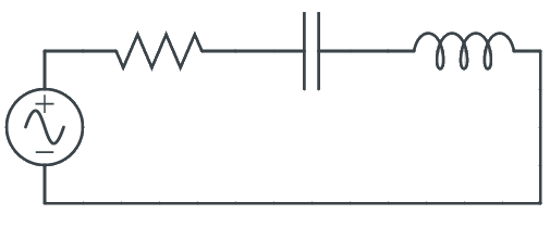
Let’s look at the series RLC circuit

What happens at the resonant frequency is that the resonant frequency is that the inductive reactance is equal and opposite to the capacitive reactance. (That’s the definition of the resonant frequency, after all!). The inductive reactance and the capacitive reactance cancel each other and that part of circuit becomes a short circuit, and with no reactance, the only thing opposing the current is the resistor. With the opposition at a minimum, the magnitude of the current will be at maximum. At other frequencies, there will be some reactance, which increases the opposition to current flow, meaning that the current at a frequency other than the resonant frequency will be less than the current at the resonant frequency.

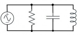
The situation is a little different for a parallel RLC circuit:

When L and C are in parallel, it behaves like an open circuit at resonance. That means that the magnitude of the current at the input is at a minimum. Ideally, no current at all would flow through L and C branches of the circuit. At frequencies other than the resonant frequency, the parallel resonant circuit will admit some current flow.

Because the L and C branches form a short circuit at the resonant frequency, any current at that frequency will simply flow around and around in that loop. We call that circulating current. Because the circulating current is flowing in a loop with very little opposition to it, it will be at maximum, but only at the resonant frequency.

Here’s a video by Stan Gibilisco, a prolific author of electronics books, has produced this video:

Filed Under: Electronics Theory

Which way does current really flow?

February 19, 2018 By Dan KB6NU 6 Comments

Last month, I received an email from a reader about the new Tech question pool. He pointed out a number issues with the questions, including some grammatical errors and inconsistencies. For example, he noted that in some questions, they used “DC” and in others, just “dc.”

It was that eye for detail that prompted me to ask him if he’d proofread the updated version of my No Nonsense Technician Class License Study Guide.  I offered to pay him, but he replied,

You do sell [your study guides], but you also make PDFs available for free. Since my #1 motivation to help would NOT be money, for now lets just evaluate how good a job I can do on an unpaid trial basis.

Then, he took me to task:

Right away I saw something there that I didn’t fully agree with. You casually say that current flows from Positive to Negative (with cool accompanying directional arrows), without any accompanying qualifying statement. Over the years I have looked at ALL the views on the subject. Positive to Negative is NOT what I was taught 48 years ago, and I have never seen a good reason to change my view. I even created a poll on QRZ to see what the general consensus would be on there. The Positive to Negative crowd did take an early lead, but my fellow Neanderthal flat earth adherents came through and powered Negative to Positive on to the victory. If you make a blanket statement that is not universally accepted, I will challenge it.

In a subsequent email, he pointed me to a Nuts ‘n Volts article, “Which Way Does Current Really Flow?” and asked my opinion. In the article, the author, who is a ham by the way, does a good job of explaining the various types of current flow.

I agree that in electronic circuits electrons flow from negative to positive, but it really doesn’t matter. I agree with the commenter Mike Huddleston who says,

This is a silly argument. It’s like comparing apples and oranges and challenging people to take sides.

Electron flow is not current flow. Electron flow is easy to understand, an actual physical property, and a real help in understanding vacuum tube operation. But it falls apart when one needs to understand complex electronic systems.

[Conventional] current flow is a mathematical abstraction. It is defined as a net flow of positive charge, irrespective of the polarity of the physical charge carriers — whether electrons, holes, positive or negative ions, or whatever.

When looking at any circuit containing a resistance with a voltage across it, conventional current through that resistor says that the voltage drop occurs as the current through it meets resistance. On the other hand, in negative (electron) flow, a voltage INCREASE will correspond to the ‘current’ flow through it, clearly violating physical laws. Conventional current flow is consistent with the laws of physics and those of other engineering disciplines.

You are correct that engineers, professors and scientists use conventional current flow. That is not because they are too obtuse to understand electron flow; I assure you they fully understand it. It is because in their world they have to solve more general problems involving complex math and science, and, again, conventional current flow is consistent with physical laws.

It is unfortunate that electron flow and current flow are so often confused. They both have their place.

I thought I’d have a look and see what the ARRL Handbook has to say about current. In the 1963 edition, they don’t mention electron flow at all. They have one diagram showing the direction of current flow in both series and parallel circuits, but the voltage source has no polarity. It’s simply labelled “Source of E.M.F.” Diagrams giving practical examples of series and parallel circuits do include a battery, and if the reader were to mash up the two diagrams, they would conclude that current flows from the positive terminal to the negative terminal.

The most recent edition of the Handbook that I have is the 2005 edition (it might be time to get another copy!). It says,

Electrons move from the negative to the positive side of the voltage, or EMF, source. Conventional current has the opposite direction, from positive to negative. This comes from an arbitrary decision made by Benjamin Franklin in the 18th century. The conventional current direction is important in establishing the proper polarity sign for many electronics calculations. Conventional current is used in much of the technical literature. The arrows in schematic symbols point in the direction of conventional current, for example.

Having said all that, I really don’t see that there’s much of a controversy here. I did learn to think of current as conventional current in college, although it was mentioned that electrons actually flow in the opposite direction. Using the concept of conventional current has never seemed to hold me back. I’ve been able to design circuits and repair electronic equipment thinking that current flows from positive to negative.

I don’t know what this all means for the next edition of my study guide. I do hope that my friend decides that he’ll proofread my study guide in spite of the fact that I’m an adherent of conventional current flow, and he’s an electron current flow guy. I am thinking of including a sidebar, similar to the paragraph above from the 2005 Handbook explaining the two ways of looking at current flow, although that’s kind of a departure from my “no nonsense” style.

What do you think?


Filed Under: Electronics Theory Tagged With: current flow

A reader writes, “Should I just grow Chia Pets as a hobby?”

December 27, 2017 By Dan KB6NU 15 Comments

A reader writes

I’m a Technician Class licensee, though I haven’t been on the air for years. What I’m looking for is instructional materials for basic electronics, radio operation, etc… I’m not an engineer, not a math whiz, and whenever I read QST, I think that I must not be too bright either :)

I’ve tried the Dummies books and other how-tos about electronics, but they all seem to assume that the reader already has some knowledge of electronics. So, after swallowing my pride I guess I settled on searching for resources that would be suitable for young kids. Would you have any suggestions (other than maybe I should just grow Chia Pets as a hobby).

I replied:

You don’t have to be an engineer to enjoy amateur radio. It’s just a hobby after all, but like any pursuit, getting started can be difficult. Actually, you’ve hit on something, I think. There aren’t really any good training materials for adults taking up the hobby. And, on top of that, many people learn better in a class setting, not by just reading books.

You don’t say what books you’ve already purchased, but one book that you might want to take a look at is The Manga Guide to Electricity. It’s not a text book, per se, but uses a story to teach about electrical and electronic principles. It’s written for kids, but even so, you probably will get something out of it.

Another book I’d recommend is Elements of Radio. It’s a book that was written to teach high-school level classes back in the 50s and 60s. It’s long been out of print, but I see that you can buy a used copy on Amazon. This is a book my father used when he was in high school.

Another thing that you might do is to get one of those kits that come with parts that you snap together to make circuits. Don’t just put the circuits together, though. In addition, get a digital multimeter (DMM), if you don’t already have one, and measure voltages and currents once you put a circuit together.

Do any of you have recommendations for this fellow? Please add them below, so that we can get this guy into the hobby.

Filed Under: Building/Homebrew, Classes/Testing/Licensing, Electronics Theory

  • « Go to Previous Page
  • Page 1
  • Page 2
  • Page 3
  • Page 4
  • Page 5
  • Page 6
  • Interim pages omitted …
  • Page 13
  • Go to Next Page »

Primary Sidebar

No Nonsense Technician Class License Study Guide (for tests given between July 2026 and June 2030)

New No Nonsense Technican Class Study Guide now available!

The 2026 version of my Tech Class study guide is now available, and as always, the PDF version is FREE!. The ePub version costs $11.97, and a Kindle version and paperback version will be available on Amazon shortly.

Click here to get all of my "No Nonsense" study guides.

Also available: The CW Geek's Guide to Having Fun with Morse Code

W5SWL.Com
Retevis Ailunce H1 DMR Radio
DXpander: Cobweb antennas, Laser Cutting

You’ve got mail!

Enter your email address below and get an email every time I publish a new post.

Email


I frequently teach classes to help newcomers get their licenses. The next class will take place on Saturday, October 10, 2026 on the University of Michigan campus. Click here for more information.

If you can't make the class, subscribe to the mailing list to be notified of when the next class will be held.

You can always download my free study guide, and if you have any questions about the classes, or amateur radio in general, please feel free to email me directly.

Support KB6NU.Com

Donate $7.30 and get two of these cool stickers. Measuring 4.25-in. W by 2.75-in. H, it's perfect for your car, your shack, or wherever!

Contact me

If you have a question or comment about one of my blog posts, or a question about any of the material in my study guides, or just a question about ham radio in general, you can email me at [email protected].

Blogs You Should Also Read

  • AE5X: A CW-centric blog from Kingswood, Texas
  • K0LWC Blog
  • LA3ZA Ham Radio Blog
  • Little Radios, Big Fun – WB3GCK
  • Mr. Vacuum Tube's Blog
  • Radio Artisan – K3NG
  • The K0NR Weblog
  • VE3WDM's QRP Ham Radio Blog
  • W2LJ’s Blog

Ham Radio Websites

  • Dashtoons – The Hammin' Comedy by Jeff K1NSS

Podcasts

  • ICQ Podcast
  • Linux in the Ham Schack
  • No Nonsense Amateur Radio Podcast
  • Resonant Frequency Amateur Radio Podcast

Recent Comments

  • mike on Instant Character Recognition is the key to CW speed
  • Matt W1CDN on A completely different picture of Wayne Green, W2NSD (SK)
  • Chana Walsh on Rethinking ham radio education
  • Rob WfourZNG on Videos: What’s next for POTA, ham radio helps rescue man trapped in cave
  • Dan KB6NU on The EMF Explorer: A badge for ham radio?

Meta

  • Log in
  • Entries feed
  • Comments feed
  • WordPress.org

Footer

Copyright © 2026 Daniel M. Romanchik, KB6NU · Log in