

• Skip to primary navigation
  • Skip to main content
  • Skip to primary sidebar
  • Skip to footer

KB6NU's Ham Radio Blog

KB6NU's Ham Radio Blog
  • HOME
  • Study Guides
  • Teach a One-Day Tech Class
  • W8SRC Repeater Guide
  • Advertise
  • Hire Me

antennas

2019 No Nonsense General Class Study Guide: Antennas and Feed Lines, part II

February 20, 2019 By Dan KB6NU 1 Comment

Directional antennas

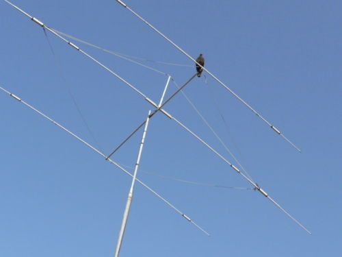
To make their signals more effective, some amateurs use directional antennas. Directional antennas, such as Yagis and quads, direct most of the power output in a particular direction, making the signal seem more powerful. They are also more sensitive to receiving signals from a particular direction. This feature makes them useful for reducing interference. All you have to do is turn the antenna away from the source of interference.

QUESTION: Which HF antenna would be the best to use for minimizing interference? (G9C11)
ANSWER: A directional antenna

The “gain” of a directional antenna is the relative increase in power radiated in the direction in which the antenna is pointing. The gain is usually specified in decibels, or dB. Look at this specification very carefully, because the gain may be specified in relation to either an isotropic antenna (dBi) or in relation to a dipole (dBd). dBi = dBd + 2.15, so if an antenna specification uses the dBi value, which is really just a theoretical value, the manufacturer is making the antenna look better than it really is.

QUESTION: What is meant by the terms dBi and dBd when referring to antenna gain? (G9C15)
ANSWER: dBi refers to an isotropic antenna, dBd refers to a dipole antenna

QUESTION: How does antenna gain stated in dBi compare to gain stated in dBd for the same antenna? (G9C04)
ANSWER: dBi gain figures are 2.15 dB higher than dBd gain figures

A characteristic related to the antenna gain is the “front-to-back ratio.” The “front-to-back ratio” of a Yagi antenna is the ratio of the power radiated in the forward direction (the main or major lobe) to the power radiated off the back of the antenna.

QUESTION: What does “front-to-back ratio” mean in reference to a Yagi antenna? (G9C07)
ANSWER: The power radiated in the major radiation lobe compared to the power radiated in exactly the opposite direction

QUESTION: What is meant by the “main lobe” of a directive antenna? (G9C08)
ANSWER: The direction of maximum radiated field strength from the antenna

Yagis are perhaps the most common type of directional antenna. A Yagi antenna consists of a driven element, a reflector, and one or more directors. The reflector and directors are called parasitic elements. The approximate length of the driven element of a Yagi antenna is ½ wavelength. The reflector is about 5% longer than the driven element, and the first director is about 5% shorter than the driven element.

What is the approximate length of the driven element of a Yagi antenna? (G9C02)
ANSWER: 1/2 wavelength

QUESTION: How do the lengths of a three-element Yagi reflector and director compare to that of the driven element? (G9C03)
ANSWER: The reflector is longer, and the director is shorter

By changing the physical characteristics of the elements and the spacing between the elements, you can change the characteristics of the antenna. For example, if you increase the diameter of the aluminum tubing that most Yagis are made from, you can increase the antenna’s bandwidth. By increasing the boom length and the number of directors, you can increase the gain of a Yagi antenna.

QUESTION: Which of the following would increase the bandwidth of a Yagi antenna? (G9C01)
ANSWER: Larger diameter elements

QUESTION: How does increasing boom length and adding directors affect a Yagi antenna? (G9C05)
ANSWER: Gain increases

QUESTION: Which of the following can be adjusted to optimize forward gain, front-to-back ratio, or SWR bandwidth of a Yagi antenna? (G9C10)
ANSWER: All of these choices are correct

  • The physical length of the boom
  • The number of elements on the boom
  • The spacing of each element along the boom

While a Yagi antenna is a great antenna, you can improve the performance of this antenna by stacking one on top of another. You get about a 3 dB gain by stacking two, three-element, horizontally polarized Yagi antennas 1/2 wavelength apart vertically. Another advantage is that it narrows the main lobe in elevation, meaning that you get a lower angle of radiation, which can be an advantage in making long-distance communications.

How does the gain of two three-element, horizontally polarized Yagi antennas spaced vertically 1/2 wavelength apart typically compare to the gain of a single three-element Yagi? (G9C09)
ANSWER: Approximately 3 dB higher

QUESTION: What is an advantage of vertical stacking of horizontally polarized Yagi antennas? (G9D05)
ANSWER: It narrows the main lobe in elevation

Although the driven element of a Yagi antenna is similar to a dipole, the other elements cause the feedpoint impedance to be significantly lower than 50 ohms. To increase the feedpoint impedance to 50 ohms, so that we can use 50-ohm feed line, many Yagis use a gamma match. One advantage of using a gamma match is that the driven element need not be insulated from the boom.

QUESTION: Which of the following is an advantage of using a gamma match with a Yagi antenna? (G9C12)
ANSWER: It does not require that the driven element be insulated from the boom

Another type of matching device used with Yagi antennas is the beta match, also called the hairpin match. A hairpin match is simply a coil connected across the coax to increase the feedpoint impedance.

QUESTION: What is a beta or hairpin match? (G9C16)
ANSWER: It is a shorted transmission line stub placed at the feed point of a Yagi antenna to provide impedance matching

You can also make directional antennas using square loop elements. The driven element loop is a full wave long, while the reflector is a little bit bigger. One advantage of a quad antenna over a Yagi is that it can be physically smaller for the same amount of gain. The forward gain of a two-element quad antenna is about the same as the forward gain of a three-element Yagi antenna.

QUESTION: Approximately how long is each side of the driven element of a quad antenna? (G9C13)
ANSWER: 1/4 wavelength

QUESTION: What configuration of the loops of a two-element quad antenna must be used for the antenna to operate as a beam antenna, assuming one of the elements is used as a reflector? (G9C06)
ANSWER: The reflector element must be approximately 5 percent longer than the driven element

QUESTION: How does the forward gain of a two-element quad antenna compare to the forward gain of a three-element Yagi antenna? (G9C14)
ANSWER: About the same


Specialized antennas

In addition to the dipole, vertical, Yagi, and beam antennas, there are many other types of antennas that you may wish to use in your station. Some of these antenna have characteristics which you may find useful in your situation.

A common variation of the dipole antenna is the inverted-V antenna. Instead of supporting the dipole at both ends of the antenna, you use a single support at the center of the antenna and stretch out the legs, forming the inverted V. The advantage of this antenna is that it requires only a single support and less horizontal space than a dipole. The sloping elements also make the feedpoint impedance closer to 50 ohms than a horizontal dipole.

QUESTION: What is the common name of a dipole with a single central support? (G9D12)
ANSWER: Inverted V

Another HF antenna that’s become popular is the horizontal loop antenna. This antenna is a wavelength or more on the lowest band it will be used on and normally fed with some type of parallel transmission line. An antenna tuner matches it to the transmitter, and because you’re using a tuner, it can be used on multiple bands.

QUESTION: What is the combined vertical and horizontal polarization pattern of a multi-wavelength, horizontal loop antenna? (G9D13)
ANSWER: Virtually omnidirectional with a lower peak vertical radiation angle than a dipole

The log-periodic antenna is one such antenna. It is called this because the length and spacing of the elements increases logarithmically from one end of the antenna to the other. It’s a directional antenna, like the Yagi, and it even resembles the Yagi, although it has more elements. Its gain, however is less than the Yagi. Its main advantage is that it has a much wider bandwidth than the Yagi antenna.

Which of the following describes a log periodic antenna? (G9D07)
ANSWER: Element length and spacing vary logarithmically along the boom

Which of the following is an advantage of a log periodic antenna? (G9D06)
ANSWER: Wide bandwidth

Another interesting antenna is the near vertical incidence sky save, or NVIS antenna. It’s designed to have a very high angle of radiation to make short-skip contacts, usually during the day. NVIS antennas are usually dipole antennas mounted close to the ground. Ground reflection give the NVIS antenna its high angle of radiation.

QUESTION: Which of the following antenna types will be most effective as a Near Vertical Incidence Skywave (NVIS) antenna for short-skip communications on 40 meters during the day? (G9D01)
ANSWER: A horizontal dipole placed between 1/10 and 1/4 wavelength above the ground

Beverage antennas are a very specialized type of antenna. They are long, low, directional antennas used for receiving on the low HF bands. Beverage antennas are not used for transmitting because they have high losses compared to other antennas.

QUESTION: What is the primary use of a Beverage antenna? (G9D09)
ANSWER: Directional receiving for low HF bands

Many antennas are designed for a single band, but in many cases, putting up an antenna for each band you want to operate is impractical. So, many amateurs put up antennas that will work on more than one band. These are called multiband antennas. Because some of the amateur radio bands are harmonically-related, one disadvantage of a multiband antenna is that it will radiate a signal’s harmonics just as well as its fundamental frequency.

QUESTION: Which of the following is a disadvantage of multiband antennas? (G9D11)
ANSWER: They have poor harmonic rejection

One type of multiband antenna is the trap vertical. Antenna traps block RF energy in a certain frequency band. This makes the antenna look shorter than it really is at that frequency. Traps are also used on Yagi antennas, so that elements can be used on multiple bands.

QUESTION: What is the primary purpose of antenna traps? (G9D04)
ANSWER: To permit multiband operation

For mobile and portable use, amateur radio operators have designed many innovative antennas. One of these is the end-fed antenna. Its main advantage is that it is easy to set up and operate when operating portable. It’s biggest disadvantage is that it requires some kind of matching unit. The reason for this is that the feedpoint has a very high impedance.

QUESTION: What is the feed-point impedance of an end-fed half-wave antenna? (G9D02)
ANSWER: Very high

Another antenna that many amateur radio operators like to use in portable operations is the magnetic loop antenna. This type of antenna has a diameter less than one-third wavelength in circumference, so it’s relatively easy to transport, and with a tripod or similar kind of stand is self-supporting. And, there are nulls in the radiation pattern broadside to the loop that you can use to reduce interference.

QUESTION: In which direction or directions does an electrically small loop (less than 1/3 wavelength in circumference) have nulls in its radiation pattern? (G9D10)
ANSWER: Broadside to the loop


For mobile operation, some amateurs use a “screwdriver” antenna. The screwdriver antenna has a motorized tuning assembly that varies the inductance of the loading coil to tune the antenna to the operating frequency.

QUESTION: How does a “screwdriver” mobile antenna adjust its feed-point impedance? (G9D08)
ANSWER: By varying the base loading inductance

For weak-signal VHF/UHF work, some amateur radio operators use a halo antenna, which is a horizontally polarized, omnidirectional, half-wavelength dipole antenna. It’s called a halo because the elements are bent into a loop with a small gap between the elements opposite the feed point. It’s a small, yet very effective antenna.

QUESTION: In which direction is the maximum radiation from a portable VHF/UHF “halo” antenna? (G9D03)
ANSWER: Omnidirectional in the plane of the halo

Filed Under: Books and Magazines, Classes/Testing/Licensing Tagged With: antennas, study guides

2015 General Class study guide: Section G9C – Directional ante2015 General Class study guide: Section G9D – Specialized antennas

February 2, 2015 By Dan KB6NU Leave a Comment

The questions in this section were unchanged.

Another type of directional antenna is the log-periodic antenna. It is called this because for a log periodic antenna, the length and spacing of the elements increases logarithmically from one end of the boom to the other. (G9D07) The gain of a log periodic antenna is less than that of a Yagi, but an advantage of a log periodic antenna is wide bandwidth. (G9D06)

The term “NVIS” means Near Vertical Incidence Sky wave when related to antennas. (G9D01) An NVIS antenna is typically installed between 1/10 and 1/4 wavelength above ground. (G9D03) An advantage of an NVIS antenna is high vertical angle radiation for working stations within a radius of a few hundred kilometers. (G9D02)

A Beverage antenna is a very long and low directional receiving antenna. (G9D10) An application for a Beverage antenna is as a directional receiving for low HF bands. (G9D09) A Beverage antenna is not used for transmitting because it has high losses compared to other antennas. (G9D08)

Many antennas are designed for a single band, but in many cases, putting up an antenna for each band you want to operate is impractical. So, many amateurs put up antennas that will work on more than one band. These are called multiband antennas. A disadvantage of multiband antennas is that they have poor harmonic rejection. (G9D11)

One type of multiband antenna is the trap vertical. Antenna traps block RF energy in a certain frequency band. This makes the antenna look shorter than it really is at that frequency. The primary purpose of antenna traps is to permit multiband operation. (G9D04)

Filed Under: Antennas, Classes/Testing/Licensing Tagged With: antennas, Beverage, log-periodic

2015 General Class study guide: Section G9C – Directional antenas

February 1, 2015 By Dan KB6NU Leave a Comment

The questions related to antenna gain were substantially changed in this question pool, and, as a result, the question numbers of other questions were changed.

To make their signals more effective, some amateurs use directional antennas. Directional antennas, such as Yagis and quads, direct most of the power output in a particular direction, making the signal seem more powerful. They are also more sensitive to receiving signals from a particular direction.

The “gain” of a directional antenna is the relative increase in power radiated in the direction in which the antenna is pointing. The gain is usually specified in decibels, or dB. Look at this specification very carefully, because the gain may be specified in relation to either an isotropic antenna (dBi) or in relation to a dipole (dBd). When referring to antenna gain, dBi refers to an isotropic antenna, dBd refers to a dipole antenna. (G9C20)

dBi is strictly a theoretical figure, as the isotropic antenna is strictly a theoretical construction. dBd is a more realistic specification. When stated in dBi, the gain of an antenna will always be higher than if it is stated in dBd. dBi gain figures are 2.15 dB higher than dBd gain figures. (G9C19)

A characteristic related to the antenna gain is the “front to back ratio.” The “front-to-back ratio” of a Yagi antenna is the power radiated in the major radiation lobe compared to the power radiated in exactly the opposite direction. (G9C07) The “major lobe” or “main lobe” of a directive antenna is the direction of maximum radiated field strength from the antenna. (G9C08)

Yagis are perhaps the most common type of directional antenna. A Yagi antenna consists of a driven element, a reflector, and one or more directors. The reflector and directors are called parasitic elements. The approximate length of the driven element of a Yagi antenna is 1/2 wavelength. (G9C02) The reflector is normally the longest parasitic element of a three-element, single-band Yagi antenna. (G9C04) In a three-element, single-band Yagi antenna, the director is normally the shortest parasitic element. (G9C03)

By changing the physical characteristics of the elements and the spacing between the elements, you can change the characteristics of the antenna. For example, larger diameter elements increase the bandwidth of a Yagi antenna. (G9C01) The gain increases when you increase boom length and add directors to a Yagi antenna. (G9C05)


All of these choices are correct when talking about Yagi antenna design variables that could be adjusted to optimize forward gain, front-to-back ratio, or SWR bandwidth (G9C10):

  • The physical length of the boom
  • The number of elements on the boom
  • The spacing of each element along the boom

While a Yagi antenna is a great antenna, you can improve the performance of this antenna by stacking one on top of another. The gain of two 3-element horizontally polarized Yagi antennas spaced vertically 1/2 wavelength apart typically is approximately 3 dB higher than the gain of a single 3-element Yagi. (G9C09) The advantage of vertical stacking of horizontally polarized Yagi antennas is that it narrows the main lobe in elevation. (G9D05)

Although the driven element of a Yagi antenna is similar to a dipole, the other elements cause the feedpoint impedance to be significantly lower than 72 ohms. The purpose of a gamma match used with Yagi antennas is to match the relatively low feed-point impedance to 50 ohms. (G9C11) An advantage of using a gamma match for impedance matching of a Yagi antenna to 50-ohm coax feed line is that it does not require that the elements be insulated from the boom. (G9C12)

You can also make directional antennas using loop antenna elements. The elements of a quad antenna are square loops. Each side of a quad antenna driven element is approximately 1/4 wavelength. (G9C13) Each side of a quad antenna reflector element is slightly more than 1/4 wavelength. (G9C15) Assuming one of the elements is used as a reflector, the reflector element must be approximately 5 percent longer than the driven element, for the antenna to operate as a beam antenna. (G9C06)

The forward gain of a two-element quad antenna is about the same as the forward gain of a three-element Yagi antenna. (G9C14) The polarization of the radiated signal changes from horizontal to vertical when the feed point of a quad antenna is changed from the center of either horizontal wire to the center of either vertical wire. (G9C18)

The elements of a delta loop beam are triangular. Each leg of a symmetrical delta-loop antenna is approximately 1/3 wavelength. (G9C17) The gain of a two-element delta-loop beam is about the same as the gain of a two-element quad antenna. (G9C16)

Filed Under: Antennas, Classes/Testing/Licensing Tagged With: antennas, quad, yagi

Antenna Installation Instructions

December 30, 2010 By Dan KB6NU Leave a Comment

On the Tacos mailing list, Mark, KB3OGD, posted the following:

I was reading the installation instructions for a particular brand of television antenna, and I thought that the last warning would be useful for all of us:  “WARNING Do not attempt to install if drunk, pregnant or both. Do not throw antenna at spouse.”

That is good advice, but I’m surprised that they actually published it.

Filed Under: Antennas Tagged With: antennas

From the Trade Mags

December 15, 2010 By Dan KB6NU Leave a Comment

I’m on the distribution list for many different electronics trade magazines. Quite often, there are articles of interest to amateur radio operators. Here are four of them—two from electronic design and two from EE Times—that I hope you’ll find interesting.

Radiated efficiency: A true measure of antenna performance
Many engineers tend to think of antennas in terms of gain, but the author argues that we’d be better off if instead we evaluated antennas in terms of efficiency, that is how well it turns the power supplied to the feedpoint into radiated energy.

And You Thought The 555 Timer Was Dead?
Recently, both Advanced Linear Devices and Semtech have redesigned the 555 timer chip, improving it in many ways and extending its usefulness—most likely—for years to come.

Melville Eastham: Workplace Innovator Crafts Early Electronic Products
Eastham was the founder of General Radio. The article points out that Eastham founded the company in 1915 to “serve the rapidly growing ham radio market.” By the late 1920s, that “boom” had subsided, and the company turned its attention to precision measurement instruments. It was very successful doing this for many, many years.

10 Technologies to Watch in 2011
This article predicts that “wireless connects for health care” will be one of the technologies to watch in 2011. Makers of medical electronics equipment, apparently, are planning to integrate their gear using Bluetooth.

Filed Under: Antennas, Electronic Components, Test Equipment Tagged With: antennas, electronics, Test Equipment

Random Links

October 16, 2010 By Dan KB6NU 3 Comments

Here are some more links to websites that ham radio ops will find amusing and/or useful:

  • Climbing a really tall tower. Ever wonder what it’s like to climb a tower nearly 1,800 feet tall? Watch this video.
  • Software for people who build things. Although some of the software on this site is fairly old, it also has an amazingly huge collection of hints and kinks on a wide variety of topics. For example, there is a great tip on how to estimate a tap or drill size.
  • Social networking for hams. Although most hams seem to be anti-social, not all of us are. This is a website for those that aren’t.
  • QRQ CW Info, Ops, and Tips. More social networking, but for hams that like to work CW at high speeds. Most of these guys go a lot faster than I can, but I’m hoping to learn something from them.

Filed Under: Antennas, Building/Homebrew, CW, Online Resources Tagged With: antennas, building/homebrewing, CW, Online Resources

Remote Tuner?

October 6, 2010 By Dan KB6NU 5 Comments

John, WA8ZPN, sent me these two photos of his remote antenna tuner:

WA8ZPN's Remote Antenna Tuner I
WA8ZPN's Remote Antenna Tuner II

My question is whether this device tunes on the fly or what?

Filed Under: Antennas Tagged With: antennas

Book Excerpt Covers Antenna Fundamentals

September 14, 2010 By Dan KB6NU 2 Comments

EETimes has posted chapters 3 and 4 from the book Antennas: Fundamentals, Design, Measurement (Third Edition). There is a little more math than ham radio operators are generally used to, but the material is useful and interesting, if you can plow through it. Here is the available material:

Chapter 3: Antenna Parameters

  • Sections 3.1 Antenna Structures; and 3.2 Radiation Pattern.
  • Sections 3.3 Directivity and Gain; 3.4 Effective Area and Friis Transmission Equation; 3.5 Beamwidth; 3.6 Minor Lobe; and 3.7 Radiation Resistance and Efficiency.
  • Sections 3.8 Input Impedance; 3.9 Bandwidth; 3.10 Polarization; 3.11 Interdependencies of Gain, Beamwidths, and Aperture Dimensions; and References, Problems and Exercises.

Chapter 4:Basic Radiators and Feed Methods

  • Section 4.1 Short Dipoles.
  • Sections 4.2 Current and Voltage in Longer Antennas; 4.3 The Half-Wave Dipole; and 4.4 Long-Wire Antennas.
  • Sections 4.5 Loop Antennas; 4.6 Helical Antennas; and 4.7 Horn Radiators.
  • Sections 4.8 Slot Radiators; 4.9 Patch or Microstrip Antennas; 4.10 Surface-Wave and Leaky-Wave Antennas; 4.11 Basic Feed Methods; and References, Problems and Exercises.

Filed Under: Antennas Tagged With: antennas

468: Ham Radio’s Magic Number

September 5, 2010 By Dan KB6NU 13 Comments

Here in the U.S.—where we still measure length in feet—468 is a magic number.  Why? Well, the formula for calculating the length, in feet, of a half-wave dipole antenna is:

L (ft) = 468 / f (MHz)

If you do the math, a half-wavelength is actually 492/f, so where did the number 468 come from? The explanation most often given these days is that a radio wave travels about 5% slower in wire than it does in free space, so the distance that a radio wave would travel in a wire is about 5% less than it would travel in free space.

Now, I don’t know about you, but while I’ve used this formula for building dipoles, I’ve never had one tune up perfectly using that number. There are a number of reasons for this, the main one being the height above ground of the dipole. What I’ve found is that the elements of the dipole are usually longer than they need to be.

I sometimes joke that whoever came up with that number did so so that hams wouldn’t cut their dipoles too short. After all, it’s much easier to make a length of wire shorter than it is to make it longer.

Ward, N0AX, wasn’t satisfied with any of the common answers to where the number 468 came from. In the latest issue of QST, he consulted the materials in the ARRL library and found the answer. The October 1926 issue of QST included an article titled, “The Length of the Hertz Antenna.” (“Hertz antenna” was the name most commonly used for a dipole in the early days of radio.)

The author of that article constructed nine different dipoles and measured their resonant frequencies. He then calculated a value, K, by which you’d multiply the wavelength to get the wire length in feet. If you multiply that number by 300, you’d get values ranging from 423 to 471.

The number 468 first appeared in the 1929 ARRL Handbook.

For this article, N0AX did a number of simulations of a 20m dipole at various heights, ranging from 1/8 wavelength to 2 wavelengths. He came up with numbers ranging from 466.4 to 483.4. This is somewhat at odds with my experience, although I must admit that I’ve never been able to get my dipoles up that high. That’s my guess for why my dipoles are almost always shorter than 468/f.

At any rate, this article is certainly worth reading.

Filed Under: Antennas Tagged With: antennas

Sea Water Antenna?

September 1, 2010 By Dan KB6NU 8 Comments

One of the items making the rounds on the HamRadioHelpGroup mailing list is this video on the Sea Water Antenna:

At first, I thought, “What a novel idea!” Of course, as the Bible says, there’s nothing new under the sun. PA1AP noted, “Reinventing the wheel I would say. There is prior? art for this and cannot be patented, they should do a little more homework and look around before making such claims… google for ‘Ionic Liquid Antenna’.”

I did just that and found a few interesting references. Apparently, N9ZRT did much of the early work on this type of antenna, and his work is online. In March 2005, some researchers published an academic paper on this topic. Unfortunately, you have to pay for this paper. Another good article can be found on the Highfields (UK) Amateur Radio Club website.

Someone from SPAWAR, the research center that produced the video, replied that in their opinion, this design is unique in that it uses a pump to produce a column of water to form the antenna. This feature makes it patentable. I’m not a patent attorney, but they may have a point here. At any rate, I’m guessing that hams should still feel free to experiment with the antenna.

Filed Under: Antennas Tagged With: antennas

  • Page 1
  • Page 2
  • Page 3
  • Go to Next Page »

Primary Sidebar

No Nonsense Technician Class License Study Guide (for tests given between July 2026 and June 2030)

New No Nonsense Technican Class Study Guide now available!

The 2026 version of my Tech Class study guide is now available, and as always, the PDF version is FREE!. The ePub version costs $11.97, and a Kindle version and paperback version will be available on Amazon shortly.

Click here to get all of my "No Nonsense" study guides.

Also available: The CW Geek's Guide to Having Fun with Morse Code

W5SWL.Com
Retevis Ailunce H1 DMR Radio
DXpander: Cobweb antennas, Laser Cutting

You’ve got mail!

Enter your email address below and get an email every time I publish a new post.

Email


I frequently teach classes to help newcomers get their licenses. The next class will take place on Saturday, February 7, 2026 on the University of Michigan campus. Click here for more information.

If you can't make the class, subscribe to the mailing list to be notified of when the next class will be held.

You can always download my free study guide, and if you have any questions about the classes, or amateur radio in general, please feel free to email me directly.

Support KB6NU.Com

Donate $7.30 and get two of these cool stickers. Measuring 4.25-in. W by 2.75-in. H, it's perfect for your car, your shack, or wherever!

Contact me

If you have a question or comment about one of my blog posts, or a question about any of the material in my study guides, or just a question about ham radio in general, you can email me at [email protected].

Blogs You Should Also Read

  • AE5X: A CW-centric blog from Kingswood, Texas
  • K0LWC Blog
  • LA3ZA Ham Radio Blog
  • Little Radios, Big Fun – WB3GCK
  • Mr. Vacuum Tube's Blog
  • Radio Artisan – K3NG
  • The K0NR Weblog
  • VE3WDM's QRP Ham Radio Blog
  • W2LJ’s Blog

Ham Radio Websites

  • Dashtoons – The Hammin' Comedy by Jeff K1NSS

Podcasts

  • ICQ Podcast
  • Linux in the Ham Schack
  • No Nonsense Amateur Radio Podcast
  • Resonant Frequency Amateur Radio Podcast

Recent Comments

  • Michael Burkhardt on One lump or two (or three)?
  • Eric on POTA notes, 7/27/26
  • Steve KB3JC on How to “ragchew” on CW
  • Dan KB6NU on Yaesu FT-710: What’s the big deal?
  • Andrei on Yaesu FT-710: What’s the big deal?

Meta

  • Log in
  • Entries feed
  • Comments feed
  • WordPress.org

Footer

Copyright © 2026 Daniel M. Romanchik, KB6NU · Log in