• Skip to primary navigation
  • Skip to main content
  • Skip to primary sidebar
  • Skip to footer

KB6NU's Ham Radio Blog

KB6NU's Ham Radio Blog
  • HOME
  • Study Guides
  • Teach a One-Day Tech Class
  • W8SRC Repeater Guide
  • Advertise
  • Hire Me

Test Equipment

From my Twitter feed: Linux propagation s/w, SMD guide

August 11, 2016 By Dan KB6NU Leave a Comment

ok2cqr's avatar
Petr Hlozek @ok2cqr
CQRPROP – HF propagation to your Linux desktop. My holiday project released! ok2cqr.com/linuxsw/how-to… #linux #hamradio #hamr

DrOrthogonal's avatar
Michael (GØPOT) @DrOrthogonal
I’ve built the rather cool @SOTAbeams Go4Lo SWR & Power Indicator…check out my overview… youtu.be/zC-o83JsWuQ
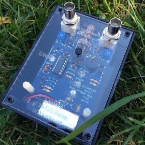
sota-beams-go4lo

ElectronicsLab's avatar
Electronics-Lab.com @ElectronicsLab
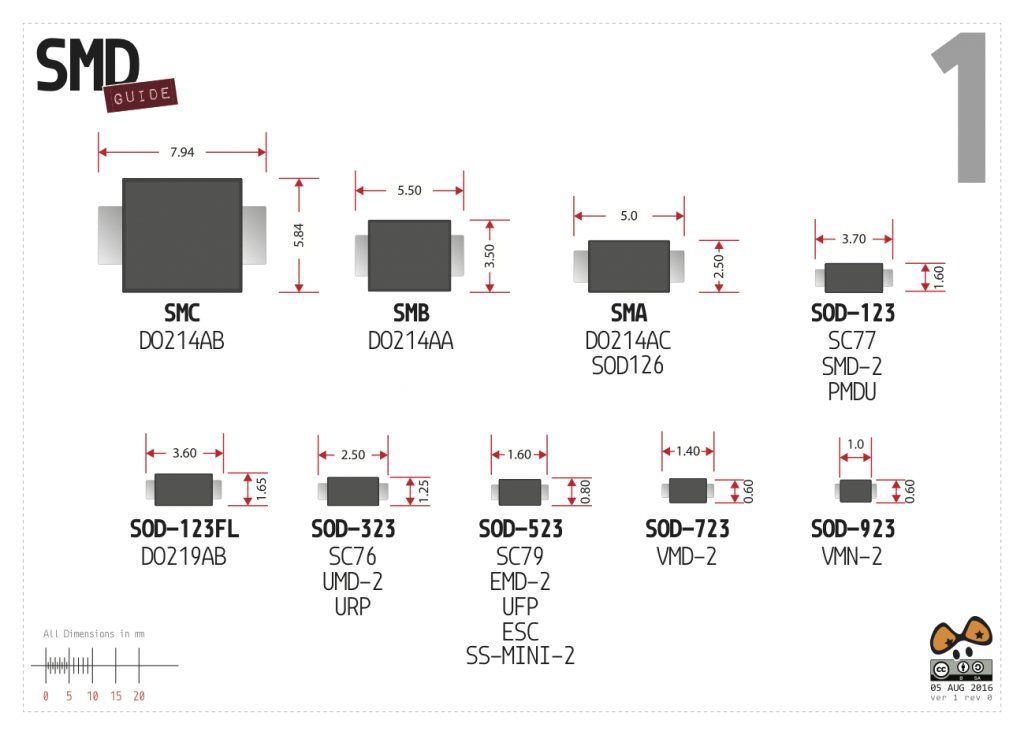
SMDGuide – A gift for all electronic enthusiasts electronics-lab.com/50802-2/
smd-guide

Filed Under: Electronic Components, Propagation, Software, Test Equipment Tagged With: power meter, surface mount

From my Twitter feed: BeagleBone logic analyzer, accuracy vs. precision, crystals

April 14, 2016 By Dan KB6NU Leave a Comment

adafruit's avatar adafruit industries @adafruit
#BeagleBone Logic Analyzer: beaglelogic 1.1 Cape adafru.it/mDn

BentTronics's avatar Bent-Tronics.com @BentTronics

A good, quick read on Accuracy vs. Precision via @FlukeCorp bit.ly/1MiogJ6 #electronics #tips #fb pic.twitter.com/ohkD1JLbyV

 RFGlobalnet's avatar RFGlobalnet @RFGlobalnet

Understanding Quartz Crystals ow.ly/10ADqM

Filed Under: Building/Homebrew, crystals, Test Equipment Tagged With: accuracy, logic analzyers, precision

2016 Extra Class study guide: E4B – Measurement techniques

March 12, 2016 By Dan KB6NU Leave a Comment

On July 1, 2020, this post will become obsolete as the 2020 Extra Class question pool goes into effect. Please refer to the post from the 2020 No Nonsense Extra Class Study Guide instead.


E4B – Measurement techniques: Instrument accuracy and performance limitations; probes; techniques to minimize errors; measurement of Q; instrument calibration

One thing about test instruments is that you need to take the readings with a grain of salt. By that, I mean that chances are that the instrument reading is not exactly the value of the parameter you’re measuring. The reason for this is that no instrument is 100% accurate.

Let’s consider frequency counters. Frequency counters are useful instruments for measuring the output frequency of amateur radio transceivers. While a number of different factors can affect the accuracy of an instrument, time base accuracy is the factor that most affects the accuracy of a frequency counter. (E4B01) The time base accuracy of most inexpensive frequency counters is about 1 part per million, or 1 ppm.

Now, let’s see how that affects the accuracy of a frequency measurement. If a frequency counter with a specified accuracy of +/- 1.0 ppm reads 146,520,000 Hz, 146.52 Hz is the most the actual frequency being measured could differ from the reading. (E4B03) Practically, what this means is that while the frequency counter reads 146,520,000 Hz, or 146.52 MHz, the actual frequency of the signal might be as low as 146.519853 Mhz or as high as 146.520147 MHz.

More accurate—and therefore more expensive—frequency counters might have a specified accuracy of .1 ppm. If a frequency counter with a specified accuracy of +/- 0.1 ppm reads 146,520,000 Hz, 14.652 Hz is the most the actual frequency being measured could differ from the reading. (E4B04) This is very accurate for amateur radio work.

Very inexpensive frequency counters might have an accuracy of only 10 ppm. If a frequency counter with a specified accuracy of +/- 10 ppm reads 146,520,000 Hz, 1465.20 Hz is the most the actual frequency being measured could differ from the reading. (E4B05) This might be adequate for amateur radio work, but as you can see, the difference between the frequency counter’s reading and the signal’s actual frequency can be up to ten times as much as with the frequency counter with a 1 ppm accuracy.

Voltmeters

Probably the most common test instrument in an amateur radio station is a voltmeter. The voltmeter may be part of a digital multimeter (DMM) or volt-ohm meter (VOM). DMMs have the advantage of high input impedance, and high impedance input is a characteristic of a good DC voltmeter. (E4B08) The higher the input impedance, the less effect the meter will have on the measurement.

The quality of a VOM is given by the VOM’s sensitivity expressed in ohms per volt. The full scale reading of the voltmeter multiplied by its ohms per volt rating will provide the input impedance of the voltmeter. (E4B12) A higher ohms per volt rating means that it will have a higher input impedance than a meter with a lower ohms per volt rating.

RF measurements

Directional power meters and RF ammeters are two instruments that you can use to make antenna measurements. With a directional power meter, you could measure the forward power and reflected power and then figure out how much power is being delivered to the load and calculate the SWR of the antenna system. For example, 75 watts is the power is being absorbed by the load when a directional power meter connected between a transmitter and a terminating load reads 100 watts forward power and 25 watts reflected power. (E4B06)

With an RF ammeter, you measure the RF current flowing in the antenna system. If the current reading on an RF ammeter placed in series with the antenna feed line of a transmitter increases as the transmitter is tuned to resonance it means there is more power going into the antenna. (E4B09)

There are a number of instruments that you can use to measure the impedance of a circuit. An antenna analyzer is one. Some sort of bridge circuit is another. An advantage of using a bridge circuit to measure impedance is that the measurement is based on obtaining a signal null, which can be done very precisely. (E4B02)

That’s the principle behind the dip meter. You adjust the meter’s controls so that the reading “dips” to a minimum value. The controls then indicate the resonant frequency. When using a dip meter, don’t couple it too tightly to the circuit under test. A less accurate reading results if a dip meter is too tightly coupled to a tuned circuit being checked. (E4B14)

For some experiments, you’ll want to know not only the resonant frequency of a circuit but also the quality factor, or Q, of the circuit. The bandwidth of the circuit’s frequency response can be used as a relative measurement of the Q for a series-tuned circuit. (E4B15)

Another type of instrument that you can use to make impedance measurements is the vector network analyzer. As with any instrument, you need to ensure that it is calibrated properly. Three test loads used to calibrate a standard RF vector network analyzer are short circuit, open circuit, and 50 ohms. (E4B17)

Finally, a method to measure intermodulation distortion in an SSB transmitter is to modulate the transmitter with two non-harmonically related audio frequencies and observe the RF output with a spectrum analyzer. (E4B10) The instrument we use to do this is called, oddly enough, a two-tone generator. Typically, these generators provide tones of 700 Hz and 1,900 Hz simultaneously.

S parameters

S-parameters, or scattering parameters, are used to describe the behavior of RF devices under linear conditions. Each parameter is typically characterized by magnitude, decibel and phase.

The subscripts of S parameters represent the port or ports at which measurements are made. (E4B07) The S parameter that is equivalent to forward gain is S21. (E4B13) The S parameter that represents return loss or SWR is S11. (E4B16)

Filed Under: Books and Magazines, Classes/Testing/Licensing, Test Equipment Tagged With: s parameters, voltmeters

2016 Extra Class study guide: E4A – Test equipment

March 11, 2016 By Dan KB6NU 1 Comment

On July 1, 2020, this post will become obsolete as the 2020 Extra Class question pool goes into effect. Please refer to the post from the 2020 No Nonsense Extra Class Study Guide instead.


E4A – Test equipment: analog and digital instruments; spectrum and network analyzers, antenna analyzers; oscilloscopes; RF measurements; computer aided measurements

An instrument that amateur radio operators frequently use when experimenting or when debugging equipment is the oscilloscope, or simply just “scope.” Oscilloscopes have become more common in amateur radio shacks as the price has fallen and the technology has moved from analog to digital.

Analog oscilloscopes use amplifiers, filters, and other analog signal processing circuits to display an input signal on a cathode-ray tube, or CRT. Digital oscilloscopes, on the other hand, use an analog-to-digital converter to convert the input signal into a series of numbers, which are then processed by a computer and displayed on an LCD screen. All of these choices are correct when talking about the advantages of a digital vs. analog oscilloscope: (E4A05)

  • Automatic amplitude and frequency numerical readout
  • Storage of traces for future reference
  • Manipulation of time base after trace capture

One of the most important oscilloscope specifications is its bandwidth. The bandwidth of an oscilloscope determines the maximum frequency at which the oscilloscope can accurately measure a signal. While the characteristics of the analog signal processing circuits determine the bandwith of an analog oscilloscope, sampling rate is the parameter that determines the bandwidth of a digital or computer-based oscilloscope. (E4A01) Similarly, the analog-to-digital conversion speed of the soundcard determines the upper frequency limit for a computer soundcard-based oscilloscope program. (E4A04)

Because digital oscilloscopes sample an input signal at discrete time intervals, it is possible to fool them into displaying an incorrect waveform. This phenomenon is called aliasing. The effect of aliasing in a digital or computer-based oscilloscope is that false signals are displayed. (E4A06) When using a computer’s soundcard input to digitize signals, the highest frequency signal that can be digitized without aliasing is one-half the sample rate. (E4A09)

Oscilloscope probes

When making measurements at RF frequencies, it’s important to connect the probe’s ground connection as close to the location of the measurement as possible. Keeping the signal ground connection of the probe as short as possible is good practice when using an oscilloscope probe. (E4A11) Keeping this connection as short as possible reduces the noise picked up by the probe and reduces the inductance of the connection, which in turn, makes the measurement more accurate..

Good quality passive oscilloscope probes have an adjustable capacitor in them that needs to be adjusted so that the probe capacitive reactance is at least nine times the scope input capacitive reactance. When this capacitor is adjusted properly, we say that the probe is properly compensated, and the scope will display the waveform with as little distortion as possible.

How is the compensation of an oscilloscope probe typically adjusted? A square wave is displayed and the probe is adjusted until the horizontal portions of the displayed wave are as nearly flat as possible. (E4A13) High-quality oscilloscopes will have a special square-wave output specifically for the purpose of compensating probes.

Spectrum analyzers

Spectrum analyzers display the amplitude of signals in the frequency domain Frequency is the parameter a spectrum analyzer would display on the horizontal axis. (E4A02) The drawing below shows typical displays from an oscilloscope and a spectrum analyzer. Spectrum analyzers are very useful for troubleshooting problems. For example, a spectrum analyzer is used to display spurious signals from a radio transmitter. (E4A03)

Because spectrum analyzers are sensitive instruments, you need to be cautious when using them. For example, an important precaution to follow when connecting a spectrum analyzer to a transmitter output is to attenuate the transmitter output going to the spectrum analyzer. (E4A12) Not doing so could damage the spectrum analyzer because its input circuits are not designed to handle high power.

Antenna analyzers

One of the instruments that I think every amateur radio operator should have (or at least have access to) is the antenna analyzer. Antenna analyzers are versatile instruments that allow amateur radio operators to easily make antenna measurements, as well as other impedance measurements. They can even be used as low power RF signal generators.

An antenna analyzer is the instrument that would be best for measuring the SWR of a beam antenna. (E4A08) Actually, it’s the best instrument for measuring the SWR of any kind of antenna. That’s what they’re made for! When measuring antenna resonance and feed point impedance with a portable antenna analyzer, connect the antenna feed line directly to the analyzer’s connector. (E4B11)

An advantage of using an antenna analyzer compared to an SWR bridge to measure antenna SWR is that antenna analyzers do not need an external RF source. (E4A07) What this means is that you don’t need to connect your transmitter to the antenna to tune it. This is because they have an internal RF signal generator.

Frequency counters, logic analyzers

To measure the frequency of a signal, you use an instrument called a frequency counter. When selecting a frequency counter, an important specification is the maximum frequency. If you want to measure the frequency of a signal whose frequency is higher than the maximum frequency of your counter, you might use a prescaler. The purpose of a prescaler function on a frequency counter is to divide a higher frequency signal so a low-frequency counter can display the input frequency. (E4A14)

Most frequency counters work by counting the number of cycles of a signal during a given time period. An alternate method of determining frequency used by some counters is period measurement plus mathematical computation. An advantage of a period-measuring frequency counter over a direct-count type is that it provides improved resolution of low-frequency signals within a comparable time period. (E4A15)

The proper operation of a digital circuit depends on the output state of many nodes at specific times in a circuit. To ensure that a circuit is working properly, or to troubleshoot a circuit, you may want to use a logic analyzer. A logic analyzer displays multiple digital signal states simultaneously. (E4A10)

Filed Under: Books and Magazines, Classes/Testing/Licensing, Test Equipment Tagged With: antenna analyzer, logic analyzer, probes, spectrum analyzer

From my Twitter feed:

March 2, 2016 By Dan KB6NU Leave a Comment

wa1gov's avatar wa1gov @wa1gov
Introduction to Ham Radio and Technician Training Class #hamradio youtu.be/RGluTpM7_K8 via @YouTube

Dave, KB9OKB, uses my  No Nonsense Technician Class License Study Guide as the basis for this video….Dan


Saelig's avatar Electrical_Engineer @Saelig
Oscilloscope Training Video 1 youtu.be/BW0K5sE2NKI?a

This is the first in a series that Saelig will produce on how to use scopes. This was just released on Monday, so you’ll have to stay tuned for more….Dan 

imabug's avatar imabug @imabug
Enginursday: KiCad and Open-Source Design sfe.io/n2041 via @sparkfun

Filed Under: Classes/Testing/Licensing, PCB design, Test Equipment Tagged With: KiCad, oscilloscope, study guides

Want to win a scope?

February 19, 2016 By Dan KB6NU 4 Comments

I got this press release from Keysight, which used to be Agilent, which used to be Hewlett-Packard, yesterday. I scanned the rules, and it doesn’t look like you have to be an electronics engineer at some big company to win one of the scopes. I just registered using KB6NU as my company name……Dan

Keysight Technologies Announces Inaugural Scope Month Event

What:

Keysight is announcing a new event for its oscilloscopes called Scope Month. Scope Month, which will take place annually during the month of March, features contests, social media activities, unprecedented access to industry experts, and more than $500,000 USD worth of oscilloscope giveaways. New winners will be announced every day.

Throughout the month, Keysight will offer in-depth information specifically developed to help engineers with their most demanding measurement challenges.

Register now to obtain access to the Scope Month content. Registrants will automatically receive an extra entry into the daily oscilloscope drawing.

When:

Registration begins Feb. 8.

Where:

Register at www.scopemonth.com.

Additional Information: www.scopemonth.com

Filed Under: Test Equipment Tagged With: Keysight, oscilloscope

Learn about oscilloscope probes

January 28, 2016 By Dan KB6NU Leave a Comment

TE-Logo-140TestEquity and Keysight are sponsoring a free webcast with Keysight on February 10 at 1 pm ET/10 am PT titled, “What’s That You Were Asking About Oscilloscope Probes?” Here’s what they have to say about the webcast:

Stay up to date on the latest technologies and solutions with complimentary Keysight webcasts. Please forward this to others that would be interested.

Why this webcast is important:
We are all familiar with them – oscilloscopes probes. We usually get one for free with each channel for the oscilloscope we purchase. Just plug the probe in and go, right? Well, not exactly. An incorrect probe or incorrect probing technique can cause faulty measurements regardless of the caliber of the oscilloscope being used.

In this webcast we will review the common types of oscilloscope probes available today – passive, active, voltage and current – and what the numbers on the probe datasheet mean. Understanding the probe specifications are key when deciding which probe to use. We will also cover proper probing techniques so that you can be confident in your measurement results.

Who should attend:
Design and test engineers, technicians, and managers.
[[I’m sure that ham radio operators would be welcome and would get a lot out of this, too….Dan]]

Register Now

Filed Under: Test Equipment Tagged With: oscilloscope, probes

From the engineering magazines: scope measurements, op-amp BW, travelling-wave tubes

January 13, 2016 By Dan KB6NU Leave a Comment

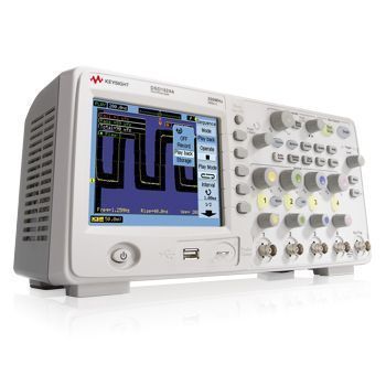
keysight-dso1000-portable-oscilloscopeMake great oscilloscope measurements. In oscilloscopes today, making a good signal measurement is easy. However, making a great measurement takes some expertise.

Op amp basics: Small signal bandwidth and overall performance. It is rare to find an op amp data sheet without a bandwidth number on the front page. Because small signal bandwidth is the largest number, this is usually the number featured most prominently. A good question, though, is how important is this number and how does it relate to other device performance metrics?

The quest for the ultimate vacuum tube. In July 1962, the Telstar 1 satellitetook an enormous leap toward the globally connected world we now take for granted. It relayed from space, for the first time ever, live television images and telephone calls between continents: specifically, a ground station in Andover, Maine, and other stations in England and France. It accomplished this feat thanks to a microwave repeater that had at its heart a slight but powerful vacuum device known as a traveling-wave tube. The 30-centimeter-long,glass-walled electron tube was at the time the only device capable of boosting a broadband television signal with enough power to cross an ocean. Solid-state devices just weren’t up to the task. More than a half century later, traveling-wave-tube amplifiers still dominate satellite communication. That’s right—your ultrahigh-definition satellite TV and satellite radio come to you courtesy of vacuum tubes in space.


Filed Under: Electronic Components, Test Equipment, Tubes

From the trade magazines: Single-board computers, oscilloscopes, tool to create custom capes

December 1, 2015 By Dan KB6NU 3 Comments

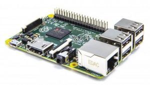
raspberrypi2Top 10 Single-Board Computers. When you’re in need of a single board computer, a vast selection is available, making it tough to pick an ecosystem. We’ll cover the top ten most current single board computers to help you choose the right platform for your next project.

Oscilloscope Measurement Webcasts from Keysight. There are links to a ton of webinars here, including Tips and Techniques for Making the Best Oscilloscope Measurements and 

Best of 2015: Create Custom Capes Fast and Easy. Geppetto is a web-based designer and build-to-order system. It supports third-party platforms like the popular BeagleBone, as well as standalone microcontrollers.

Filed Under: Microcontrollers, Test Equipment

Don’t toss it. Fix it!

October 27, 2015 By Dan KB6NU 9 Comments

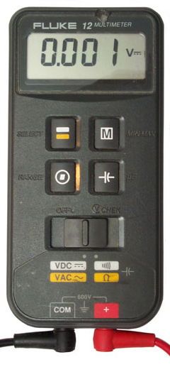
Last night, in the afterglow of successful sales at the USECA Hamfest on Sunday morning, I was going through the junk I’ve collected over the years, looking for stuff to sell at the next hamfest. One thing that I came across was a Fluke Model 12 multimeter. Fluke gave me this meter to review way back when I was an editor for Test&Measurement World magazine.

fluke-12-dmmThe Fluke 12 is an interesting meter because the controls are so different. Instead of using a big rotary switch found on most DMMs, to choose the measurement type you have to set the slide switch to one of two settings, then hit the button in the upper left-hand corner. In practice, users must have found this a bit confusing as the Fluke 12B, the next model in this line, went back to the big rotary switch.

At any rate, I pulled the meter out of the box, inserted a 9 V battery, and switched it on. I was very disappointed to find that many of the LCD segments were either not working or appeared to be only half on. Not only that, none of the function switches seemed to be working. I tried a different 9 V battery just in case, but got the same results as with the first battery.

At that point, the thought crossed my mind to just chuck it. The meter is at least 25 years old, and even though I rarely used it, it was given to me, so I wasn’t really out any money. After thinking about it a little, though, I thought I’d take it apart to see if there were any obvious problems that I could easily fix.

To get the meter apart, you have to first unscrew four screws from the rear, then lift off the rear part of the case. What you see at this point is the rear of the main board, which snaps into the front part of the case. To find the problem, I was going to somehow extract the main board.

This was easy enough to do. All I needed was a small screwdriver, which allowed me to pry the board from the case. There were even a couple of notches in the PCB to allow one to do this more easily.

zebra_s_eThe first thing that I noticed was a set of pads up near the top of the main board. As it turns out, these pads are for the signals that drive the LCD segments. The signals are connected to the LCD via a “flexible, zebra connector strip, as shown at right. The connector strip is made of a spongy silicone material and when the main board is pressed into the front part of the case, this zebra strip connects the main board to the LCD.

Since my first rule of troubleshooting is to check the connections, the first thing that I did was to run my finger along both the pads on the main board and then on the zebra strip. After I did this, I snapped the main board in, and powered up the meter. Like magic, the LCD now had no bad segments.

The function switches still weren’t working, though. I popped the board out again to take a look. Sure enough, there was a smaller zebra strip that connected the main board to the switch board. I ran my finger over the pads on the main board and the zebra strip connector, snapped the board back into the case, and powered up the meter again. I was very happy to see that now the function switches worked as well, and I had a functional DMM.

The point of all this is to encourage you to do a little tinkering with some non-functional electronics that you might have or might be able to get for cheap at some hamfest. Many, if not most, of the problems you’ll encounter are with the connectors and cabling, and a lot of times, these are easy fixes. At best, you’ll have fixed something and now have something useful. At worst, you’ll have learned something for a small investment of time and money.


Filed Under: Building/Homebrew, Test Equipment

  • « Go to Previous Page
  • Page 1
  • Interim pages omitted …
  • Page 6
  • Page 7
  • Page 8
  • Page 9
  • Page 10
  • Interim pages omitted …
  • Page 15
  • Go to Next Page »

Primary Sidebar

No Nonsense Technician Class License Study Guide (for tests given between July 2026 and June 2030)

New No Nonsense Technican Class Study Guide now available!

The 2026 version of my Tech Class study guide is now available, and as always, the PDF version is FREE!. The ePub version costs $11.97, and a Kindle version and paperback version will be available on Amazon shortly.

Click here to get all of my "No Nonsense" study guides.

Also available: The CW Geek's Guide to Having Fun with Morse Code

W5SWL.Com
Retevis Ailunce H1 DMR Radio
DXpander: Cobweb antennas, Laser Cutting

You’ve got mail!

Enter your email address below and get an email every time I publish a new post.

Email


I frequently teach classes to help newcomers get their licenses. The next class will take place on Saturday, February 7, 2026 on the University of Michigan campus. Click here for more information.

If you can't make the class, subscribe to the mailing list to be notified of when the next class will be held.

You can always download my free study guide, and if you have any questions about the classes, or amateur radio in general, please feel free to email me directly.

Support KB6NU.Com

Donate $7.30 and get two of these cool stickers. Measuring 4.25-in. W by 2.75-in. H, it's perfect for your car, your shack, or wherever!

Contact me

If you have a question or comment about one of my blog posts, or a question about any of the material in my study guides, or just a question about ham radio in general, you can email me at [email protected].

Blogs You Should Also Read

  • AE5X: A CW-centric blog from Kingswood, Texas
  • K0LWC Blog
  • LA3ZA Ham Radio Blog
  • Little Radios, Big Fun – WB3GCK
  • Mr. Vacuum Tube's Blog
  • Radio Artisan – K3NG
  • The K0NR Weblog
  • VE3WDM's QRP Ham Radio Blog
  • W2LJ’s Blog

Ham Radio Websites

  • Dashtoons – The Hammin' Comedy by Jeff K1NSS

Podcasts

  • ICQ Podcast
  • Linux in the Ham Schack
  • No Nonsense Amateur Radio Podcast
  • Resonant Frequency Amateur Radio Podcast

Recent Comments

  • Michael Burkhardt on One lump or two (or three)?
  • Eric on POTA notes, 7/27/26
  • Steve KB3JC on How to “ragchew” on CW
  • Dan KB6NU on Yaesu FT-710: What’s the big deal?
  • Andrei on Yaesu FT-710: What’s the big deal?

Meta

  • Log in
  • Entries feed
  • Comments feed
  • WordPress.org

Footer

Copyright © 2026 Daniel M. Romanchik, KB6NU · Log in