 I’m going to steal an idea from my friend, Steve Leibson. He recently wrote a book review of Designing Electronics That Work by Hunter Scott, and I found the book so good that I thought I’d write a review of my own. TL;DR: This is a great book, and what makes it even greater is that the PDF version is free. (Print copies are available for $39.)
As Scott says in the preface, “This book is a collection of tips, techniques, and tricks that generally take a small amount of time and effort to implement, but have a disproportionate effect on the outcome of a design.”
Here’s an RF example:
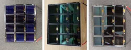
High-speed and RF signals require high Q (quality factor) capacitors. Capacitor manufacturers have specific product lines for high frequency use. If you use a regular, non-high Q capacitor, bad things will happen: your filters won’t have the response you expect, your amplifiers will oscillate, and you’ll see very high insertion loss through your capacitors. It is critical that you choose capacitors that are rated for the frequency that you’re using. The GJM capacitor series by Murata (their high Q series) has a self-resonant frequency of 16 GHz. Johanson is another good manufacturer of high Q capacitors.
The book is chockfull of such examples on all phases of product design. He starts with how to set product requirements and specifications, how to specify and buy parts, how to build prototypes, keeping a lab notebook, how to design a schematic, how to layout a PC board, and how to test and troubleshoot designs.
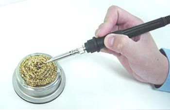
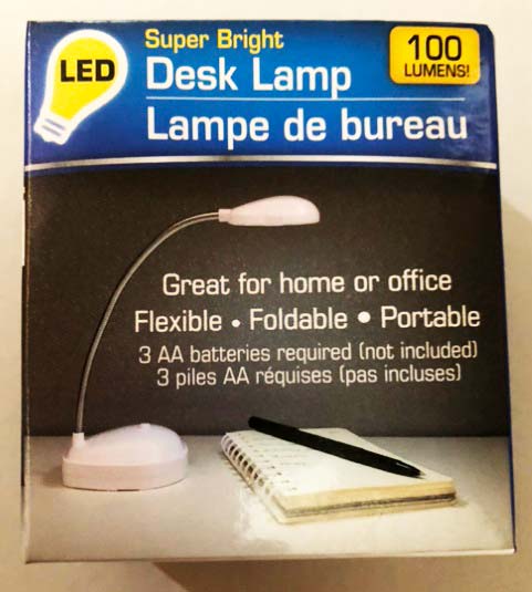
There’s also a chapter on how to outfit an electronics lab. Here’s an excerpt from that chapter:
A lab needs excellent lighting. Get ring lights for your microscopes and very bright overhead lights for the lab bench. When you’re dealing with parts that are hundredths of an inch long, you don’t want any shadows. You also want the light to be as white as possible to make discolorations of parts easier to see.
Scott wrote this book for professional electronics design engineers, but nearly all of the advice is applicable to amateur radio. Amateurs may not have to be as rigorous as professional engineers, but adopting some of the practices described in this book will help hams be more successful when designing and building your own projects.