• Skip to primary navigation
  • Skip to main content
  • Skip to primary sidebar
  • Skip to footer

KB6NU's Ham Radio Blog

KB6NU's Ham Radio Blog
  • HOME
  • Study Guides
  • Teach a One-Day Tech Class
  • W8SRC Repeater Guide
  • Advertise
  • Hire Me

Test Equipment

Build your own resistor load bank

August 6, 2020 By Dan KB6NU Leave a Comment

I’ve written many blog posts about power supplies and electronic loads for AMETEK Programmable Power. This has been interesting to do, and I’ve learned a fair amount about power supplies and electronic loads. So much so, I’d really like to get an electronic load of my own. The only problem is that they’re still a bit out of my price range.

A couple of days ago, though, I ran across the article, Versatile Multistep Resistor Load Bank is Simple and Modular in electronic design. It’s a relatively simple design that consists of a number of resistors and switches, as shown in the figure below.
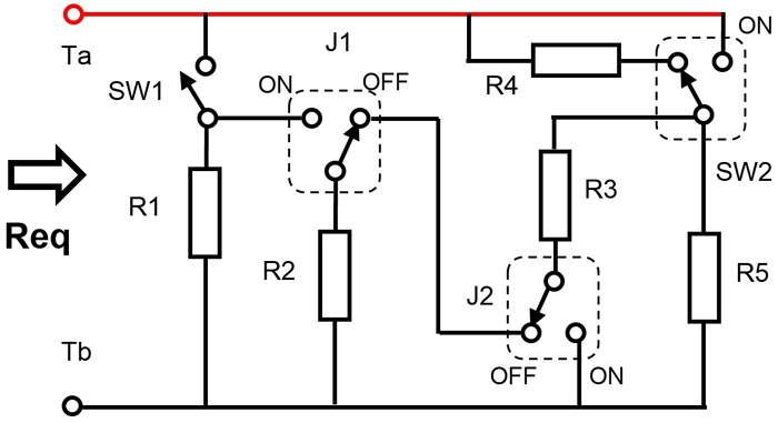
R1 – R5 are all the same value, and in this configuration, you can realize 12 different values, from R/4 to 2R. Here’s how you would set the switches to get these resistance values:
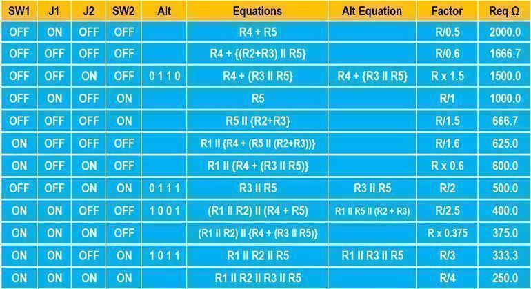
The right-most column on this chart shows the values you’d realize when R = 1000 Ω.

As the author notes, you can cascade load banks to get even more values. You could also build more than one load bank with different resistance values. If you used 100 Ω resistors, the lowest resistance value would be 25 Ω, and with 10 Ω resistors, the lowest value would be 2.5 Ω.

This looks like it could be a very useful project to build, and the opportunities to be creative with the packaging are endless.

Filed Under: Test Equipment Tagged With: resistor load bank

From the “pro” magazines: LM386 regen, IEEE Spectrum on ham radio, measure resonator Q factor

June 9, 2020 By Dan KB6NU 4 Comments

Create radio receiver circuits with the LM386 audio amplifier

I didn’t have much luck using an LM386 as an audio amplifier (I needed more output power), but perhaps I’ll have more success using it to make a regenerative receiver. I think that I even have all the parts in my junk box.

Here’s a schematic from the article:

Is Ham Radio a Hobby, a Utility…or Both? A Battle Over Spectrum Heats Up

This was actually last summer’s controversy, but while the arguments about WinLink have cooled down, it’s still an issue. I used to be quite anti-WinLink, but since it seems to really be useful for emergency communications, I’m less strident about it than I used to be. I just searched fcc.gov to see if I could find out what’s going on with RM-11831, and was surprised to see that as recently as April 3, 2020, there were still comments being filed. So, I guess it ain’t over until it’s over.

Determining Resonator Q Factor from Return-Loss Measurement Alone

The author uses an expensive VNA from his employer, Copper Mountain Technologies, but with a little ingenuity, you can probably do with your $60 NanoVNA.

Filed Under: Building/Homebrew, Rules, Regulations, Enforcement, Test Equipment Tagged With: nanoVNA, regen, WinLink

From my Twitter feed: How to remove battery corrosion, how to use your NanoVNA, another Chinese SDR

June 5, 2020 By Dan KB6NU Leave a Comment

Here are some things I found useful or interesting on Twitter in the last couple of days…Dan


If you’re like me, you’ve had batteries leak in one or more devices. Here’s the tl;dw version:

  1. Brush off loose corrosion.
  2. Add lemon juice or vinegar and continue brushing.
  3. Scrape off what’s left.
  4. Clean battery compartment.
  5. Wipe with a clean cloth.

NanoVNA presentation

Wondering what you can do with one of these neat, little devices besides measure SWR? Well, this presentation from Dan, KW4TI, will give you some ideas, including:

  1. Find the electrical length of a piece of coax.
  2. Measure the value of components.
  3. Measure the impedance of a balun.
  4. Make antenna measurements like you would with an antenna analyzer.

Chinese SDR

Ailunce is giving folks a sneak peak at their HS2 HF VHF UHF SDR Transceiver. It boasts a frequency range of 300 kHz – 1.6 GHz, a built-in network port for remote operation, and an output power of 30 W on HF among a host of other features. And the price? Only $500.
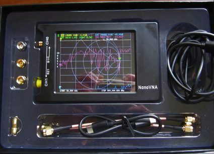
If this thing actually works, it could be a very attractive purchase. We’ll find out in September.


Filed Under: Gear/Gadgets, Repair/Maintenance, Software-Defined Radio (SDR), Test Equipment

Amateur radio videos: CQ music videos, scope tips

April 28, 2020 By Dan KB6NU 3 Comments

This video popped up on the amateurradio sub-reddit. I’d heard this song before, but I wasn’t aware that a record had actually been given out at a Hamvention. Pretty cool, don’t you think?

This is really my favorite, though. Although there’s some debate about where he was born, some say Slim Gaillard was a Detroit native. So, I have that connection. I wanted to use this music as the theme song, for my podcast, but couldn’t figure out if someone still held the copyright to this song.

Just so this blog post isn’t totally devoid of technical content, here are some scope tips from
Rohde & Schwarz. Some of these tips are R&S-specific, but the first two—maximizing the waveform display and compensating your probes—are good tips for any scope. Now, I’m beginning to wonder when I adjusted my scope probe compensation.

Filed Under: Test Equipment

Got my NanoVNA!

April 14, 2020 By Dan KB6NU 5 Comments

After waiting more than a week, my NanoVNA arrived yesterday! It’s a NanoVNAH4 from R&L Electronics. With shipping, it cost me $67.80.

I haven’t really had a chance to do anything with it yet, but so far, I’m pretty impressed. It came in a nice box, and included the following accessories:

  • USB Type-C data cable
  • 2 – 15cm SMA male to male RG316RF cable
  • SMA male calibration kit – OPEN, SHORT, LOAD
  • SMA female to female connector
  • Type-c to Type-c cable

It does not come with SMA – UHF or SMA – BNC adapters. I just happen to have an SMA-UHF adapter, but I wish I’d also purchased an SMA – BNC adapter. If you plan on purchasing this unit, you might want to consider what kind of adapters you’ll need and get them at the same time.

It does not come with a user manual, which is par for the course these days, but it did have a sheet showing how to navigate the menu system, which allowed me to play around with it. This morning, after a bit of googling, I found the github repository and the user guide.

As I say, I haven’t had a chance to put it through its paces, but I did put the LOAD, which is a 50 Ω load, and read a pretty flat 1:1 SWR from 50 kHz – 1.5 GHz.

One of the big complaints about the NanVNA has been the small screen. Not only is the small screen hard to read, the on-screen menu buttons are practically useless for most users who have big fingers. That’s why I paid extra for the larger screen. With reading glasses, I found the 4-in. screen relatively easy to read, and since I have relatively small fingers, I am actually able to navigate the menus using the on-screen buttons.

Next, I’m going to connect it to my 2m/70cm j-pole and see what kind of frequency response it has. After that, I’ll probably check out some bandpass filters.

If you already have a NanoVNA, what have you used it for? What “gotchas” should I be aware of?

Filed Under: Test Equipment Tagged With: nanoVNA

Amateur radio videos I’ve been watching: NanoVNA, calling CQ, 1970s ham radio

April 10, 2020 By Dan KB6NU 1 Comment

I just ordered a NanoVNAH4 from R&L Electronics. While waiting for it to arrive, I decided to watch a few videos. I haven’t watched a ton of them yet, but two things occur to me. First the really basic videos are almost too basic for me. I’m an electronics engineer by training, though, so what’s too basic for me might be a really good introduction for most. The second thing is that since it’s open source, nanoVNA designs are changing on the fly, so videos made six months ago may be woefully out of date.

Having said that, I like this video because W0QE is an engineer and he brings that experience to this video. He talks my language. He points out some of the shortcomings of the unit he bought (and nanoVNAs in general), but overall thinks they are worthwhile tools.

This is a good look at one of our most basic operating practices.

This is an amusing look back on ham radio in the 1970s.

Filed Under: History, Operating, Test Equipment Tagged With: nanoVNA

2020 Extra Class study guide: E4B – Measurement technique and limitations: instrument accuracy and performance limitations; probes; techniques to minimize errors; measurement of Q; instrument calibration; S parameters; vector network analyzers

March 21, 2020 By Dan KB6NU Leave a Comment

When making measurements, you should keep in mind that test instruments are not 100% accurate. What that means is that the instrument reading is not exactly the value of the parameter you’re measuring. The reading is always going to be off by some amount.

Let’s consider frequency counters. Frequency counters are useful instruments for measuring the output frequency of amateur radio transceivers. While a number of different factors can affect the accuracy of an instrument, time base accuracy is the factor that most affects the accuracy of a frequency counter. The time base accuracy of most inexpensive frequency counters is about 1 part per million, or 1 ppm. So, if you were measuring a frequency of 146.520 MHz with a frequency counter with a specified accuracy of +/- 1.0 ppm, the measured frequency could vary by as much as 146.52 Hz, meaning that the frequency counter could as low as 146.519853 MHz or as high as 146.520147 MHz.

QUESTION: Which of the following factors most affects the accuracy of a frequency counter? (E4B01)
ANSWER: Time base accuracy

Voltmeters

Probably the most common test instrument in an amateur radio station is a voltmeter. The voltmeter may be part of a digital multimeter (DMM) or volt-ohm meter (VOM). DMMs have the advantage of high input impedance. The higher the input impedance, the less effect the meter will have on the measurement.

The input impedance of a VOM is calculated using the VOM’s sensitivity expressed in ohms per volt. The full scale reading of the voltmeter multiplied by its ohms per volt rating will provide the input impedance of the voltmeter. A higher ohms per volt rating means that it will have a higher input impedance than a meter with a lower ohms per volt rating.

QUESTION: What is the significance of voltmeter sensitivity expressed in ohms per volt? (E4B02)
ANSWER: The full scale reading of the voltmeter multiplied by its ohms per volt rating will indicate the input impedance of the voltmeter

RF measurements

Directional power meters and RF ammeters are two instruments that you can use to make antenna measurements. With a directional power meter, you could measure the forward power and reflected power and then figure out how much power is being delivered to the load and calculate the SWR of the antenna system. For example, if you measure 100 watts of forward power and 25 watts reflected power with a directional wattmeter when you connect it between a transmitter and a terminating load, then you know that 75 watts is being absorbed by the load. If your load is an antenna, you can then calculate the SWR of the antenna system using these values.

QUESTION: How much power is being absorbed by the load when a directional power meter connected between a transmitter and a terminating load reads 100 watts forward power and 25 watts reflected power? (E4B06)
ANSWER: 75 watts

With an RF ammeter, you measure the RF current flowing in an antenna system. If you connect an RF ammeter in series with the antenna feed line of a transmitter, you should find that the RF current increases as the transmitter is tuned to resonance. This means there is more power going into the antenna.

QUESTION: What is indicated if the current reading on an RF ammeter placed in series with the antenna feed line of a transmitter increases as the transmitter is tuned to resonance? (E4B09)
ANSWER: There is more power going into the antenna

For some designs, you’ll want to know not only the resonant frequency of a circuit but also the quality factor, or Q, of the circuit. As we noted in the chapter on antennas, circuits with a high Q have a narrower bandwidth than circuits with a lower Q. Determining the bandwidth of a series-tuned circuit’s frequency response can, therefore, be used to measure the Q of the circuit.

QUESTION: Which of the following can be used to measure the Q of a series-tuned circuit? (E4B08)
ANSWER: The bandwidth of the circuit’s frequency response

A test that’s often used to measure intermodulation distortion in an SSB transmitter is called the two-tone test. To perform this test, you modulate the transmitter with two audio frequency signals that are not harmonically related audio frequencies and observe the RF output with a spectrum analyzer. The instrument that provides the audio frequency signals is called, oddly enough, a two-tone generator, and typically, these generators provide tones of 700 Hz and 1,900 Hz simultaneously.

QUESTION: Which of the following methods measures intermodulation distortion in an SSB transmitter? (E4B10)
ANSWER: Modulate the transmitter using two AF signals having non-harmonically related frequencies and observe the RF output with a spectrum analyzer

Vector network analyzers, S parameters

An instrument that you might use to make these measurements is a vector network analyzer. As with any instrument, you first need to ensure that it is calibrated properly. Three test loads used to calibrate a standard RF vector network analyzer are short circuit, open circuit, and 50 ohms.

QUESTION: Which of the following can be measured with a vector network analyzer? (E4B11)
ANSWER: All these choices are correct

    • Input impedance
    • Output impedance
    • Reflection coefficient

QUESTION: What three test loads are used to calibrate an RF vector network analyzer? (E4B05)
ANSWER: Short circuit, open circuit, and 50 ohms

You can also use vector network analyzer to measure S-parameters, or scattering parameters. S-parameters describe the behavior of RF devices under linear conditions. Each parameter is typically characterized by magnitude, decibel and phase. The subscripts of S parameters represent the port or ports at which measurements are made. The S parameter that is equivalent to forward gain is S21.The S parameter that represents return loss or SWR is S11.

QUESTION: What do the subscripts of S parameters represent? (E4B07)
ANSWER: The port or ports at which measurements are made

QUESTION: Which S parameter is equivalent to forward gain? (E4B03)
ANSWER: S21

QUESTION: Which S parameter represents input port return loss or reflection coefficient (equivalent to VSWR)? (E4B04)
ANSWER: S11

Filed Under: 2020 Extra Class Study Guide, Test Equipment

2020 Extra Class study guide: E4A – Test equipment: analog and digital instruments; spectrum analyzers; antenna analyzers; oscilloscopes; RF measurements; computer-aided measurements

March 20, 2020 By Dan KB6NU Leave a Comment

An instrument that amateur radio operators frequently use when experimenting or when debugging equipment is the oscilloscope, or simply just “scope.” Oscilloscopes have become more common in amateur radio shacks as prices have fallen, and the technology has moved from analog to digital.
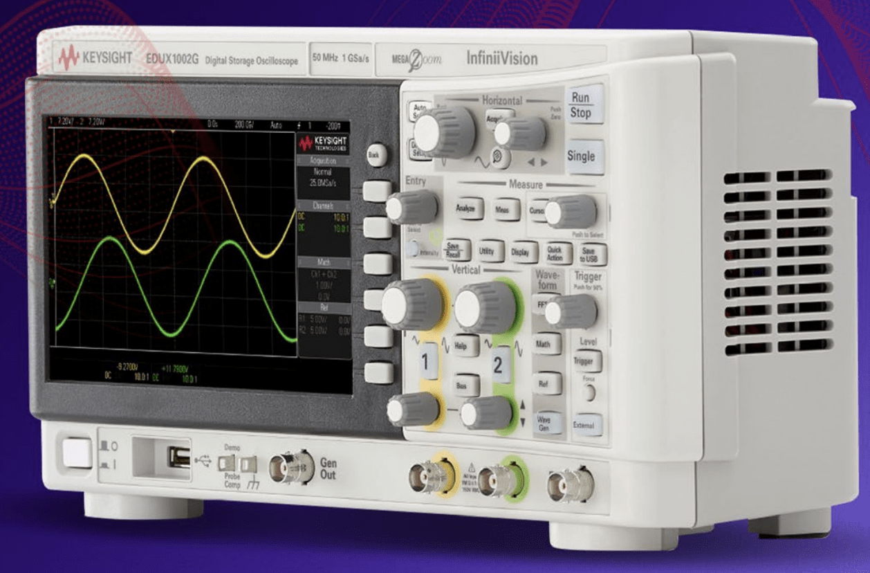
One of the most important oscilloscope specifications is its bandwidth. The bandwidth of an oscilloscope determines the maximum frequency at which the oscilloscope can accurately measure a signal. Several factors determine the highest frequency signal that can be accurately displayed on a digital oscilloscope, including the characteristics of the analog signal processing circuits and the sampling rate of the scope’s analog-to-digital converter.

QUESTION: Which of the following limits the highest frequency signal that can be accurately displayed on a digital oscilloscope? (E4A01)
ANSWER: Sampling rate of the analog-to-digital converter

While digital scopes have many advantages over analog scopes, you have to know how to use them properly. For example, because digital oscilloscopes sample an input signal at discrete time intervals, it is possible to fool them into displaying an incorrect waveform. This phenomenon is called aliasing. If you set the time base too slow, the scope may display a false, jittery version of the input signal.

QUESTION: What is the effect of aliasing on a digital oscilloscope caused by setting the time base too slow? (E4A06)
ANSWER: A false, jittery low-frequency version of the signal is displayed

Oscilloscope probes

When making measurements at RF frequencies, it’s important to connect the probe’s ground connection as close to the location of the measurement as possible. Keeping the signal ground connection as short as possible reduces the noise picked up by the probe and reduces the inductance of the connection, which in turn, makes the measurement more accurate.

QUESTION: Which of the following is good practice when using an oscilloscope probe? (E4A09)
ANSWER: Keep the signal ground connection of the probe as short as possible

Good quality passive oscilloscope probes have an adjustable capacitor in them that needs to be adjusted so that the probe capacitive reactance is at least nine times the scope input capacitive reactance. When this capacitor is adjusted properly, we say that the probe is properly compensated, and the scope will display the waveform with as little distortion as possible.

Most oscilloscopes have a special square-wave output specifically for the purpose of compensating probes. To adjust the compensation, you connect the probe to this output and then adjust the probe until the horizontal portions of the displayed wave are as nearly flat as possible.

QUESTION: How is the compensation of an oscilloscope probe typically adjusted? (E4A04)
ANSWER: A square wave is displayed and the probe is adjusted until the horizontal portions of the displayed wave are as nearly flat as possible

Spectrum analyzers

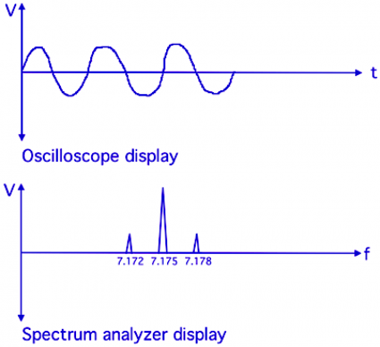
While oscilloscopes display the amplitude of a signal over time, spectrum analyzers display the amplitude of the frequency components of a signal. As shown in the figure below, the horizontal axis of an oscilloscope display represents time, while the horizontal axis of a spectrum analyzer display represents frequency. For both instruments, the vertical axis represent the amplitude of the signal being measured.

Spectrum analyzers are very useful for troubleshooting problems. For example, a spectrum analyzer is used to display spurious signals or intermodulation distortion products generated by an SSB transmitter.

QUESTION: Which of the following parameters does a spectrum analyzer display on the vertical and horizontal axes? (E4A02)
ANSWER: RF amplitude and frequency
QUESTION: Which of the following test instruments is used to display spurious signals and/or intermodulation distortion products generated by an SSB transmitter? (E4A03)
ANSWER: A spectrum analyzer

Antenna analyzers

One of the instruments that I think every amateur radio operator should have (or at least have access to) is the antenna analyzer. Antenna analyzers are versatile instruments that allow amateur radio operators to easily make antenna measurements, as well as other impedance measurements. They can even be used as low power RF signal generators. One of the most common uses for an antenna analyzer is measuring the SWR of an antenna system.

An advantage of using an antenna analyzer compared to an SWR bridge to measure antenna SWR is that antenna analyzers do not need an external RF source. What this means is that you don’t need to connect your transmitter to the antenna to tune it. This is because antenna analyzers have internal RF signal generators.

You can also make related measurements, such as the antenna resonant frequency and feed point impedance with an antenna analyzer. To make these measurements you connect the antenna feed line directly to the analyzer’s connector.

QUESTION: Which of the following measures SWR? (E4A08)
ANSWER: An antenna analyzer

QUESTION: Which of the following is an advantage of using an antenna analyzer compared to an SWR bridge to measure antenna SWR? (E4A07)
ANSWER: Antenna analyzers do not need an external RF source

QUESTION: How should an antenna analyzer be connected when measuring antenna resonance and feed point impedance? (E4A11)
ANSWER: Connect the antenna feed line directly to the analyzer’s connector

Frequency counters, logic analyzers

To measure the frequency of a signal, you use an instrument called a frequency counter. When selecting a frequency counter, an important specification is the maximum frequency. If you want to measure the frequency of a signal whose frequency is higher than the maximum frequency of your counter, you might use a prescaler. A prescaler divides a higher frequency signal so a low-frequency counter can display the input frequency.

QUESTION: What is the purpose of the prescaler function on a frequency counter? (E4A05)
ANSWER: It divides a higher frequency signal so a low-frequency counter can display the input frequency

The proper operation of a digital circuit depends on the output state of many digital ICs at specific times. To ensure that a circuit is working properly, or to troubleshoot a circuit, you may want to use a logic analyzer because it displays multiple digital signal states simultaneously.

QUESTION: Which of the following displays multiple digital signal states simultaneously? (E4A10)
ANSWER: Logic analyzer

Filed Under: 2020 Extra Class Study Guide, Test Equipment Tagged With: antenna analyzers, oscilloscopes, spectrum analyzers

Keysight on Scopes

December 14, 2019 By Dan KB6NU 1 Comment

I get a lot of email from Keysight, which used to be Agilent, which used to be Hewlett Packard (HP). I like getting this stuff because I like keeping up with what’s going on in the electronics test and measurement world. A lot of it is promotional material, but there’s a lot of good info, too.

In particular, they’ve been sending me a lot of email about oscilloscopes lately. In late September, they sent me a link to the ebook, “A Step Beyond the Basics: 6 Advanced Oscilloscope Tips.” 

In mid-October, they wrote, “Access best practices that help you get the most out of your oscilloscope and enable you to make more accurate measurements. Learn the basics of triggering, how to choose the right probe, proper signal scaling, how to select the right acquisition mode and more. Download the eBook 6 Essential Tips for Getting the Most Out of Your Oscilloscope to begin improving your test results today!”

And, a week ago, their email pointed me towards the Oscilloscope Basics Toolkit. “Access popular tips that have helped hundreds of engineers with triggering, scaling signals, selecting the right bandwidth, removing noise from signals, and more,” they say.

Here’s a tip from 6 Essential Tips for Getting the Most Out of Your Oscilloscope:

Remember Probing Matters

Choose the right oscilloscope probe Probes are used to connect your oscilloscope to your device under test (DUT), and they are crucial for optimizing signal integrity. There are literally hundreds of different oscilloscope probes available, so how do you choose the right one? There’s no single answer because all designs are different. But, here are some different probe characteristics you’ll want to consider before making a decision.

Bandwidth

A probe’s bandwidth describes how high of a frequency the probe is able to pass on to the oscilloscope. Your probes should be at least 3x to 5x faster than the fastest signal you want to see.

Attenuation ratio

Probes have different (sometimes switchable) attenuation ratios that change how the signals are fed into your oscilloscope. A higher attenuation ratio will allow you to look at higher voltages, but it will also make the scope’s internal amplifier noise more pronounced. Low attenuation ratios means you’ll see less scope noise but have more system loading distorting your signal.

Filed Under: Test Equipment Tagged With: oscilloscopes

Open browser windows: Characterize a low-pass filter with a scope and signal generator, Hackspace magazine, shortcomings of virtual communications

October 27, 2019 By Dan KB6NU Leave a Comment

I haven’t tried this yet, but it looks like a good way to characterize a filter without a spectrum analyzer.


HackSpace is a magazine that looks to be directed at Raspberry Pi users, but hams use Raspberry Pis, don’t we? In issue #24, there are at least two articles that I found interesting:

  • Making and tuning antennas: Sending and receiving data the most efficient way.
  • Get FM radio on a microntroller: Link your Arduino up to the airwaves and get some banging tunes.

Neither article is amateur radio specific, but the concepts could easily be adapted to amateur radio.


The Many Shortcomings of Virtual Communication. I’m thinking of starting a webinar-like amateur radio class and using Zoom so that students from around the country can attend. That’s what made this article of interest to me.

It’s a short book review of the new book Can You Hear Me? How to Connect with People in a Virtual World. Even though it’s a book review, it does have a tip or two on how to make virtual communication more effective. One of them is t ask the attendees how they’re doing before beginning the webinar. The helps make a personal connection and engages the attendees at least a little bit, which hopefully leads to keeping them engaged and interested throughout the webinar.

More about the virtual ham radio classes in an upcoming blog post.

Filed Under: Gear/Gadgets, Microcontrollers, Test Equipment Tagged With: oscilloscope, RPi, sig gen

  • « Go to Previous Page
  • Page 1
  • Page 2
  • Page 3
  • Page 4
  • Page 5
  • Interim pages omitted …
  • Page 15
  • Go to Next Page »

Primary Sidebar

No Nonsense Technician Class License Study Guide (for tests given between July 2026 and June 2030)

New No Nonsense Technican Class Study Guide now available!

The 2026 version of my Tech Class study guide is now available, and as always, the PDF version is FREE!. The ePub version costs $11.97, and a Kindle version and paperback version will be available on Amazon shortly.

Click here to get all of my "No Nonsense" study guides.

Also available: The CW Geek's Guide to Having Fun with Morse Code

W5SWL.Com
Retevis Ailunce H1 DMR Radio
DXpander: Cobweb antennas, Laser Cutting

You’ve got mail!

Enter your email address below and get an email every time I publish a new post.

Email


I frequently teach classes to help newcomers get their licenses. The next class will take place on Saturday, February 7, 2026 on the University of Michigan campus. Click here for more information.

If you can't make the class, subscribe to the mailing list to be notified of when the next class will be held.

You can always download my free study guide, and if you have any questions about the classes, or amateur radio in general, please feel free to email me directly.

Support KB6NU.Com

Donate $7.30 and get two of these cool stickers. Measuring 4.25-in. W by 2.75-in. H, it's perfect for your car, your shack, or wherever!

Contact me

If you have a question or comment about one of my blog posts, or a question about any of the material in my study guides, or just a question about ham radio in general, you can email me at [email protected].

Blogs You Should Also Read

  • AE5X: A CW-centric blog from Kingswood, Texas
  • K0LWC Blog
  • LA3ZA Ham Radio Blog
  • Little Radios, Big Fun – WB3GCK
  • Mr. Vacuum Tube's Blog
  • Radio Artisan – K3NG
  • The K0NR Weblog
  • VE3WDM's QRP Ham Radio Blog
  • W2LJ’s Blog

Ham Radio Websites

  • Dashtoons – The Hammin' Comedy by Jeff K1NSS

Podcasts

  • ICQ Podcast
  • Linux in the Ham Schack
  • No Nonsense Amateur Radio Podcast
  • Resonant Frequency Amateur Radio Podcast

Recent Comments

  • Michael Burkhardt on One lump or two (or three)?
  • Eric on POTA notes, 7/27/26
  • Steve KB3JC on How to “ragchew” on CW
  • Dan KB6NU on Yaesu FT-710: What’s the big deal?
  • Andrei on Yaesu FT-710: What’s the big deal?

Meta

  • Log in
  • Entries feed
  • Comments feed
  • WordPress.org

Footer

Copyright © 2026 Daniel M. Romanchik, KB6NU · Log in