• Skip to primary navigation
  • Skip to main content
  • Skip to primary sidebar
  • Skip to footer

KB6NU's Ham Radio Blog

KB6NU's Ham Radio Blog
  • HOME
  • Study Guides
  • Teach a One-Day Tech Class
  • W8SRC Repeater Guide
  • Advertise
  • Hire Me

Test Equipment

NIST radio station WWV celebrates a century of service

October 2, 2019 By Dan KB6NU Leave a Comment

From NIST’s Taking Measure Blog:

What technological application has had musical, timekeeping, navigational, scientific, traffic-control, emergency-response, and telephone applications?

Answer: WWV, one of the world’s oldest continuously operating radio stations.

NIST received the call letters WWV a century ago, in 1919. Since then, it has operated the station from several different locations — originally Washington, D.C., then a succession of locales in Maryland, and now Fort Collins, Colorado.

The programming is rather dry but very, very useful. WWV broadcasts time and frequency information 24 hours a day, seven days a week, to millions of listeners worldwide.

…read more

Filed Under: SWLing, Test Equipment

WWV Festival of Frequency Measurement

September 22, 2019 By Dan KB6NU Leave a Comment

From the subreddit /r/amateurradio…..

WWV is the US broadcast center of frequency distribution and measurement. In that spirit, during our centennial special event, WW0WWV is sponsoring frequency measurement as part of its activities. It will operate in full-carrier AM mode part of the time at an announced, accurate frequency and invite listeners to calibrate their receivers against its carrier. The station will also, on request, measure amateur station’s AM carriers and report their transmitted accuracy to them and include it on their QSO certificate. The involved WW0WWV station will be an NIST-traceable measurement system.

The Amateur Radio Science-Citizen Initiative, HamSCI, is also hosting a distributed data collection event. Amateurs, shortwave listeners, and others are invited to make a computer record of WWV 5 MHz signal’s Doppler shift during the centennial day, 1 October 2019 UTC. Resulting files may be uploaded for research analysis to a common server. Details and instructions may be found on HamSCI’s website, https://hamsci.org/wwv-centennial-festival-frequency-measurements

Filed Under: Gear/Gadgets, Test Equipment

All kinds of stuff on Twitter today: new rig from Icom, NanoVNA video, 2m safe after all

August 30, 2019 By Dan KB6NU 4 Comments

There are a lot of cool #hamradio discussions going on on Twitter lately. Instead of just copying and pasting Tweets like I usually do, though, I think I’ll discuss the topics.

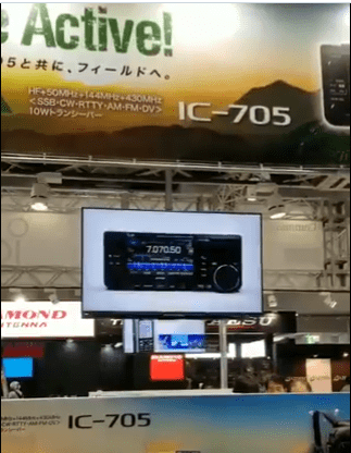
IC-705 at Japan Ham Fair

ICOM leaked a short video of the folks setting up the booth at Ham Fair 2019, Japan’s answer to the Dayton Hamvention. The video shows a small, KX3-like radio with a built-in spectrum scope. In the video, the screen shows various features of the IC-705, including VHF and UHF bands as well as HF coverage, an output of 10W, and a Bluetooth interface. This looks like a very cool radio to me.

UPDATE: There’s more detailed information about the IC-705 on hamlife.jp.

NanoVNA

The Nano Vector Network Analyzer (VNA) has been getting a lot of attention lately. Rather, I should say that the Chines knockoffs of the NanoVNA have gotten a lot of attention lately. These devices are only $50, and by all accounts they seem to be more than adequate for amateur radio use. Here’s a a beginners guide to the Nano VNA:

2 m safe after all

Ham radio operators all over the world got their knickers in a twist a couple of months ago over a proposal by the French government to make the Aeronautical Mobile Service the primary users of the 144-146 MHz band and demote the Amateur Radio Service to secondary users. It actually sounded kind of serious, but I guess pundits like your truly jumped the gun on this.

As the Radio Amateurs of Canada report in the story, Update on Two Metres Sharing Proposal Countdown to World Radiocommunication Conference 2019,

At the meeting of the Conference Preparatory Group of the Conseil Europëen des Postes et Radiocommunication (CEPT) – which concluded on August 30 in Ankara, Turkey – France modified its proposal that the International Telecommunication Union (ITU) study several frequency segments for sharing with the Aeronautical Mobile Service and withdrew the 144 to 146 MHz segment from the proposal. This welcome development was the result of an energetic and professional representation by delegates from the International Amateur Radio Union (IARU).

The ARRL also reported on this story, but I wanted to work the word “metres” into this blog post.

Filed Under: Gear/Gadgets, Test Equipment, VHF/FM/Repeaters

From my Twitter feed: Measuring SWR, Linux for #hamradio, soldering flux

August 25, 2019 By Dan KB6NU Leave a Comment

Siglent_Tech's avatar

SIGLENT TECHNOLOGIES @Siglent_Tech

W8BYA compares different techniques for measuring SWR on antennas: youtube.com/watch?v=Ui7fP9…


ke2yk's avatar
KE2YK_HAMRADIO @ke2yk

Download KB1OIQ – Andy’s Ham Radio Linux on SourceForge for free! Ubuntu Linux remastered for Amateur Radio users sourceforge.net/projects/kb1oi


digikey's avatar

Digi-Key Electronics @digikey

Why use #flux when #soldering? Learn More –> dky.bz/2XXnP1C

Filed Under: Building/Homebrew, Computers, Test Equipment

Random stuff: Girl Scouts, junque, test instrument webinars

July 29, 2019 By Dan KB6NU 3 Comments

Episode385 of Freakonomics (July 17, 2019),  “What Do Nancy Pelosi, Taylor Swift, and Serena Williams Have in Common?” features an interview with Silvia Acevedo, the CEO of Girl Scouts. Acevedo is a rocket scientist and tech executive with advanced degrees from Stanford. In this episode, she talks about her career in tech and how the Girl Scouts are now encouraging girls to explore science and technology. That being the case, it might be time to see if we can start working with Girl Scouts again.


On the Flying Pigs QRP mailing list, Harold, KE6TI wrote, “Twenty years ago, or more, I managed a program run by the RCA ARC in Indianapolis. Basically we had a bunch of parts that were surplus to the club’s needs and in too small quantities (mostly) to sell to surplus dealers.  So we put a list up on the club’s website and offered them free to anybody, only asking to be reimbursed for postage.  We also limited quantities so we weren’t supplying hoarders or resellers.”

To which, Diz, W8DIZ, of kitsandparts.com fame, replied, “I think I will just create a type of bulletin board for people to contact each other…a meeting place for “junque.” http://junque.org will be operational very soon. junque.org is indeed online, but there’s nothing really there yet. Stay tuned, though.

In the meantime, read my blog post about the importance of a junk in amateur radio.


Keysight, which used to be Agilent, which used to be Hewlett-Packard, has posted ten webinars that cover benchtop test equipment topic, including:

  • 10 Things You Must Know About DMMs
  • Four Tricks You Didn’t Know You Can Do With Waveform Generators
  • How Resourceful Engineers Get the Most Out of Their Waveform Generators
  • Battery Life Measurement Theory and Testing Techniques
  • Test at Breakneck Speeds with System Power Supplies
  • Making Sense of Wireless Sensor Power Consumption
  • Fundamentals of Voltage and Current IV Measurements
  • Overcoming Resistance and Picoammeter Measurement Challenges
  • Automating Everyday Test and Measurement Tasks in Minutes

You can access them by clicking here. You do have to give them  your name and email address, but  you can opt-out of getting a lot of spam from them. The webinars are heavily weighted to using Keysight instruments, but there’s a lot of good info in them, too.

Filed Under: Building/Homebrew, Kids, QRP, Test Equipment

Cool stuff in my Twitter feed today

May 24, 2019 By Dan KB6NU Leave a Comment

qz's avatar
Quartz@qz

Learning Morse code is a valuable skill—even in the 21st century ow.ly/4uiS30oOEan


hackaday's avatar
hackaday@hackaday

Way to improve your frequency counter’s accuracy. hackaday.com/2019/05/23/imp…


pe4bas's avatar

Bas @pe4bas

Proppy HF propagation circuit prediction tool dlvr.it/R5LL48

Filed Under: CW, Propagation, Test Equipment

2019 No Nonsense General Class Study Guide: Amateur Radio Practices, part I

February 25, 2019 By Dan KB6NU 2 Comments

Station operation and set up

Modern HF transceivers have features that make operating a breeze, but to use them properly, you have to know when to use them and how to use them. The notch filter is a good example. The notch filter actually introduces a notch into a receiver’s passband to block interfering signals.

QUESTION: What is the purpose of the “notch filter” found on many HF transceivers? (G4A01)
ANSWER: To reduce interference from carriers in the receiver passband

Another feature that helps reduce interference from nearby stations is the IF shift control. It shifts the passband of the IF filter to the right or left of the center frequency.

QUESTION: Which of the following is a use for the IF shift control on a receiver? (G4A11)
ANSWER: To avoid interference from stations very close to the receive frequency

One type of interference is called overload. This occurs when a strong incoming signal is close to the frequency that you’re monitoring. To help prevent this type of interference, many transceivers have an attenuator, which you can switch in to reduce the signal level reaching the RF amplifiers.

QUESTION: What is one reason to use the attenuator function that is present on many HF transceivers? (G4A13)
ANSWER: To reduce signal overload due to strong incoming signals

Noise is quickly becoming a big problem for amateur radio operators, whether it be from power lines, atmospheric noise, or man-made noise from electronic devices in one’s home or neighbors’ homes. To combat this, most modern transceivers have noise blankers and noise reducers. Noise blankers attempt to reduce pulse type noise, such as from a car ignition, by reducing the receiver gain during a noise pulse. Noise reducers are designed to reduce the level from other types of noise. One disadvantage of a noise reducer is that when you increase the noise reduction level, the incoming signal may become distorted.

QUESTION: How does a noise blanker work? (G4A16)
ANSWER: By reducing receiver gain during a noise pulse

QUESTION: What happens as the noise reduction control level in a receiver is increased? (G4A17)
ANSWER: Received signals may become distorted

Modern transceivers also have features that make operating CW more convenient and effective. For example, most transceivers nowadays have built-in electronic keyers. Keyers automatically generate dots and dashes (dits and dahs) of exactly the same length and evenly space them as well.


Another feature designed for easier CW operation is the ability to select which sideband that you want to use to receive a CW signal. This feature can reduce or eliminate interference from signals in the receiver passband. By selecting the opposite, or “reverse,” sideband, you shift the receiver’s passband up or down, so that the interfering signal can no longer be heard.

QUESTION: What is the purpose of an electronic keyer? (G4A10)
ANSWER: Automatic generation of strings of dots and dashes for CW operation

QUESTION: What is one advantage of selecting the opposite, or “reverse,” sideband when receiving CW signals on a typical HF transceiver? (G4A02)
ANSWER: It may be possible to reduce or eliminate interference from other signals

Many modern transceivers also have the ability to receive on one frequency and send on another. This is called “split mode.” Some high-end transceivers also have two or more variable frequency oscillators, or VFOs. Both of these features allow you to receive on one frequency and transmit on another.

These features are especially useful when operating DX, that is when contacting foreign stations. You set your receiver frequency to the frequency on which the DX station is calling and your transmitter frequency to a frequency that won’t interfere with the DX station. That allows everyone to hear the DX station and allows the DX station operator to hear and call stations trying to call him or her. If your radio has only a single VFO, it switches rapidly between the transmit and receive frequencies. If your radio has two VFOs, it can monitor both frequencies simultaneously.

QUESTION: What is normally meant by operating a transceiver in “split” mode? (G4A03)
ANSWER: The transceiver is set to different transmit and receive frequencies

QUESTION: Which of the following is a common use for the dual-VFO feature on a transceiver? (G4A12)
ANSWER: To permit monitoring two different frequencies

It has become quite popular to operate “digital modes” by supplying an audio signal, usually from a computer sound card, to a transceiver set to transmit single sideband. This type of operation is called audio frequency shift keying, or AFSK, because the audio tones will shift the transmitted frequency.

In order to send a clean signal, you must set the mic gain and automatic level control (ALC) properly. If not set properly, your signal could become distorted and you might actually transmit spurious signals.

QUESTION: What is likely to happen if a transceiver”s ALC system is not set properly when transmitting AFSK signals with the radio using single sideband mode? (G4A14)
ANSWER: Improper action of ALC distorts the signal and can cause spurious emissions

One problem that may occur when transmitting AFSK signals is that the audio cable or USB cable connecting the computer to the radio may pick up stray RF. Should this happen, your signal might become distorted or the radio might be disconnected from the computer.

QUESTION: Which of the following can be a symptom of transmitted RF being picked up by an audio cable carrying AFSK data signals between a computer and a transceiver? (G4A15)
ANSWER: All of these choices are correct
– The VOX circuit does not un-key the transmitter
– The transmitter signal is distorted
– Frequent connection timeouts

Many amateurs buy linear amplifiers to make their signals stronger. Knowing how to set the controls on a linear amplifier, including the load or coupling control, ALC, and drive power, is important so that you transmit clean signals and avoid damaging the amplifier.

QUESTION: What is the correct adjustment for the load or coupling control of a vacuum tube RF power amplifier? (G4A08)
ANSWER: Maximum power output without exceeding maximum allowable plate current

QUESTION: What reading on the plate current meter of a vacuum tube RF power amplifier indicates correct adjustment of the plate tuning control? (G4A04)
ANSWER: A pronounced dip

QUESTION: What is a reason to use Automatic Level Control (ALC) with an RF power amplifier? (G4A05)
ANSWER: To reduce distortion due to excessive drive

QUESTION: What condition can lead to permanent damage to a solid-state RF power amplifier? (G4A07)
ANSWER: Excessive drive power

When using a linear amplifier, a time delay is sometimes included in a transmitter keying circuit. The reason for this is to give the system time to completelyl change over from receive to transmit operation.

QUESTION: Why is a time delay sometimes included in a transmitter keying circuit? (G4A09)
ANSWER: To allow time for transmit-receive changeover operations to complete properly before RF output is allowed

Antenna tuners, also known as antenna couplers, are also common accessories in an amateur radio station. They ensure a good match between the transmitter and the antenna system.

QUESTION: What type of device is often used to match transmitter output impedance to an impedance not equal to 50 ohms? (G4A06)
ANSWER: Antenna coupler or antenna tuner

Test and monitoring equipment, two-tone test

When you set up your amateur radio station, sometimes called your “shack,” you’ll not only want to acquire radios, but also some test equipment. The most basic piece of test equipment is the voltmeter. Voltmeters may be either analog or digital, but most amateurs now choose digital meters because they are cheaper and more accurate than analog meters. One of the reasons that digital voltmeters are more accurate is that they have a higher input impedance than analog voltmeters. The higher input impedance reduces the load on the circuit being tested, and thereby improves the accuracy.

QUESTION: What is an advantage of a digital voltmeter as compared to an analog voltmeter? (G4B06)
ANSWER: Better precision for most uses
QUESTION: Why is high input impedance desirable for a voltmeter? (G4B05)
ANSWER: It decreases the loading on circuits being measured

The use of an analog meter might, however, be preferred over a digital meter in some applications. The reason for this is that with an analog meter you can more easily see how a circuit’s output changes as you tune it.

QUESTION: What is an instance in which the use of an instrument with analog readout may be preferred over an instrument with a digital readout? (G4B14)
ANSWER: When adjusting tuned circuits

An oscilloscope is another handy piece of test equipment to have in your shack. With an oscilloscope, you can see how the amplitude of complex waveforms change over time. To do this, they have both vertical and horizontal amlifiers, that let you adjust the scale of the amplitude and the time period that you see on the screen.

QUESTION: What item of test equipment contains horizontal and vertical channel amplifiers? (G4B01)
ANSWER: An oscilloscope

QUESTION: Which of the following is an advantage of an oscilloscope versus a digital voltmeter? (G4B02)
ANSWER: Complex waveforms can be measured

One application for an oscilloscope is to check the keying waveform of a CW transmitter. With an oscilloscope, you can see how fast the RF signal reaches full amplitude when the transmitter is keyed, and how quickly the signals falls off when the key is released. Because oscilloscopes are not designed to handle high power, you must attenuate the transmitter output before connecting the oscilloscope.

QUESTION: Which of the following is the best instrument to use when checking the keying waveform of a CW transmitter? (G4B03)
ANSWER: An oscilloscope

QUESTION: What signal source is connected to the vertical input of an oscilloscope when checking the RF envelope pattern of a transmitted signal? (G4B04)
ANSWER: The attenuated RF output of the transmitter

Antenna analyzers are instruments that can measure a number of different parameters associated with antennas, such as SWR and coaxial cable impedance. To make measurements with an antenna analyzer, you disconnect the antenna system from the transmitter and connect it to the analyzer. One problem that you may encounter is that nearby transmitters can affect measurements that you make with an antenna analyzer. The reason for this is that the antenna being analyzed will pick up RF energy from the nearby transmitters, and this energy will be read as excessive reflected power.

QUESTION: Which of the following must be connected to an antenna analyzer when it is being used for SWR measurements? (G4B11)
ANSWER: Antenna and feed line

QUESTION: What is a use for an antenna analyzer other than measuring the SWR of an antenna system? (G4B13)
ANSWER: Determining the impedance of coaxial cable

QUESTION: What problem can occur when making measurements on an antenna system with an antenna analyzer? (G4B12)
ANSWER: Strong signals from nearby transmitters can affect the accuracy of measurements

Another instrument that you can use to make SWR measurements is a directional wattmeter. To measure the SWR with a direction wattmeter, you first measure the forward power, then the reverse power, and finally calculate the SWR with the equation: SWR = (1 + √(Pr/Pf))/(1- √(Pr/Pf)).

QUESTION: Which of the following can be determined with a directional wattmeter? (G4B10)
ANSWER: Standing wave ratio

The field strength meter is another instrument useful for making antenna measurements. You can use a field strength meter to make relative field strength readings, and by making a series of these readings in a circle around an antenna determine the antenna’s radiation pattern.

QUESTION: Which of the following instruments may be used to monitor relative RF output when making antenna and transmitter adjustments? (G4B08)
ANSWER: A field-strength meter

QUESTION: Which of the following can be determined with a field strength meter? (G4B09)
ANSWER: The radiation pattern of an antenna

To test the linearity of an SSB transmitter, you run a test called the two-tone test. You modulate the transmitter with two non-harmonically related tones, usually 700 Hz and 1900 Hz. If the transmitter is perfectly linear, those two tones will appear on the output. If not, non-linear products of those two frequencies will appear on the transmitter output, and you’ll be able to detect those products using an oscilloscope or spectrum analyzer.

QUESTION: What type of transmitter performance does a two-tone test analyze? (G4B15)
ANSWER: Linearity

QUESTION: What signals are used to conduct a two-tone test? (G4B07)
ANSWER: Two non-harmonically related audio signals

Filed Under: Books and Magazines, Classes/Testing/Licensing, Gear/Gadgets, Test Equipment Tagged With: study guides

Videos: Canadians on antenna fundamentals, PLUTO SDR, Fluke standards lab

February 5, 2019 By Dan KB6NU Leave a Comment

Antenna Fundamentals: Propagation

If you’re not quite sure how an antenna radiates a signal, this video should help you visualize that. If you’re of a certain age, tell me that you don’t think of The Outer Limits when the narrator starts talking.

PLUTOSDR Tutorial

The Analog Devices ADALM-PLUTO SDR Active Learning Module (PlutoSDR) is a module that introduces the fundamentals of software-defined radio (SDR), radio frequency (RF), and wireless communications to electrical engineering students.It looks like a very cool device to me. Mouser has them for $140.


A visit to the Fluke standards lab

Being a bit of a measurement nerd, I love calibration and standards labs.  This video focuses on the calibration of cable testers, but the principles apply to other electronics instrumentation as well. It’s a bit hypey, but I found it pretty interesting as well.


Filed Under: Antennas, Software-Defined Radio (SDR), Test Equipment

Ham radio videos: AR glasses, measuring AC voltages safely with a scope, the Three Stooges copy some Morse Code

November 30, 2018 By Dan KB6NU Leave a Comment

Here’s what Jeri Ellsworth, AI6TK, has been up to lately:


Be careful measuring AC mains voltages!


And, who doesn’t love the Three Stooges? (Well, my wife, for one, but she’s not a ham.)

Filed Under: Everything Else, Gear/Gadgets, Test Equipment

75, 50, and 25 Years Ago in QST: VTVM, direct conversion receiver, loop antennas

November 13, 2018 By Dan KB6NU 1 Comment

One of the features that I like in QST is the 75, 50, and 25 Years Ago column in the back of the book. This month, there are a wealth of interesting, and possibly still useful articles, from those back issues. Here are my selections:

November 1943

The U.S. was still at war in 1943. There is plenty of news about amateurs serving in the armed forces, and the editorial describes plans for a postwar future when we will be back on the air.

A V.T. Voltmeter for A.C. and D.C. by A. D. Mayo, W4CBD. What I found amusing about this is the subtitle, “A simple unit easily constructed from available parts.” It uses four tubes, none of which are readily available anymore. Neither is the meter, for that matter. Here’s the schematic:

November 1968

Incentive licensing went into effect on November 22, 1968. This was a big deal then as General Class licensees, who had full privileges at the time, actually had some privileges taken from them. The editorial touted it as “one of a number of ways to strengthen amateur radio.”

There are a bunch of construction articles in this issue, including “Direct Conversion: A Neglected Technique,” which describes a simple, transistorized 80m receiver, and “ICKEY—An Integrated Circuit Electronic Keyer with Dot and Dash Memories.” Dot and dash memories allow the keyer to do iambic keying. The circuit is relatively simple, and might even be fun to play around with.

November 1993

Two articles caught my eye in the November 1993 issue. The first, “An Update on Compact Transmitting Loops,” looks to be a pretty good article on this type of antenna. There’s been a lot of interest in them lately, so give this article a read.

The second, “A Simple, Two-Tone Audio Generator” describes a three-transistor circuit that that generates one or both of the two audio tones that you’d use for “SSB transmitter testing, power-amplifier linearity checks, and other general audio troubleshooting and adjustments.”


Filed Under: Books and Magazines, Building/Homebrew, Gear/Gadgets, Receivers, Test Equipment, Tubes

  • « Go to Previous Page
  • Page 1
  • Page 2
  • Page 3
  • Page 4
  • Page 5
  • Page 6
  • Interim pages omitted …
  • Page 15
  • Go to Next Page »

Primary Sidebar

No Nonsense Technician Class License Study Guide (for tests given between July 2026 and June 2030)

New No Nonsense Technican Class Study Guide now available!

The 2026 version of my Tech Class study guide is now available, and as always, the PDF version is FREE!. The ePub version costs $11.97, and a Kindle version and paperback version will be available on Amazon shortly.

Click here to get all of my "No Nonsense" study guides.

Also available: The CW Geek's Guide to Having Fun with Morse Code

W5SWL.Com
Retevis Ailunce H1 DMR Radio
DXpander: Cobweb antennas, Laser Cutting

You’ve got mail!

Enter your email address below and get an email every time I publish a new post.

Email


I frequently teach classes to help newcomers get their licenses. The next class will take place on Saturday, February 7, 2026 on the University of Michigan campus. Click here for more information.

If you can't make the class, subscribe to the mailing list to be notified of when the next class will be held.

You can always download my free study guide, and if you have any questions about the classes, or amateur radio in general, please feel free to email me directly.

Support KB6NU.Com

Donate $7.30 and get two of these cool stickers. Measuring 4.25-in. W by 2.75-in. H, it's perfect for your car, your shack, or wherever!

Contact me

If you have a question or comment about one of my blog posts, or a question about any of the material in my study guides, or just a question about ham radio in general, you can email me at [email protected].

Blogs You Should Also Read

  • AE5X: A CW-centric blog from Kingswood, Texas
  • K0LWC Blog
  • LA3ZA Ham Radio Blog
  • Little Radios, Big Fun – WB3GCK
  • Mr. Vacuum Tube's Blog
  • Radio Artisan – K3NG
  • The K0NR Weblog
  • VE3WDM's QRP Ham Radio Blog
  • W2LJ’s Blog

Ham Radio Websites

  • Dashtoons – The Hammin' Comedy by Jeff K1NSS

Podcasts

  • ICQ Podcast
  • Linux in the Ham Schack
  • No Nonsense Amateur Radio Podcast
  • Resonant Frequency Amateur Radio Podcast

Recent Comments

  • Michael Burkhardt on One lump or two (or three)?
  • Eric on POTA notes, 7/27/26
  • Steve KB3JC on How to “ragchew” on CW
  • Dan KB6NU on Yaesu FT-710: What’s the big deal?
  • Andrei on Yaesu FT-710: What’s the big deal?

Meta

  • Log in
  • Entries feed
  • Comments feed
  • WordPress.org

Footer

Copyright © 2026 Daniel M. Romanchik, KB6NU · Log in