Some of these operators are just amazing…
One of the most encouraging things in amateur radio is the renewed interest at the college level. Here’s an example:
Just for fun, here’s a little electronics theory….
Some of these operators are just amazing…
One of the most encouraging things in amateur radio is the renewed interest at the college level. Here’s an example:
Just for fun, here’s a little electronics theory….
On the amateur radio subreddit, some guy posted a link to his ePay store where he’s selling fancy crystal radios. Since there’s a rule that you can’t post ads, his post was quickly removed, but not before I clicked on a link and got a look at his work. Honestly, some of it looked pretty interesting, but there was one thing he was selling that I questioned.
One of his products is a little board with four germanium diodes in parallel (see below). I’m going to guess that these are 1N34A diodes. When I asked him what the purpose was for connecting four diodes in parallel like that, he replied, “To decrease the Diode Resistance so it improves the Diode performance in a Crystal Radio (his caps, not mine).”
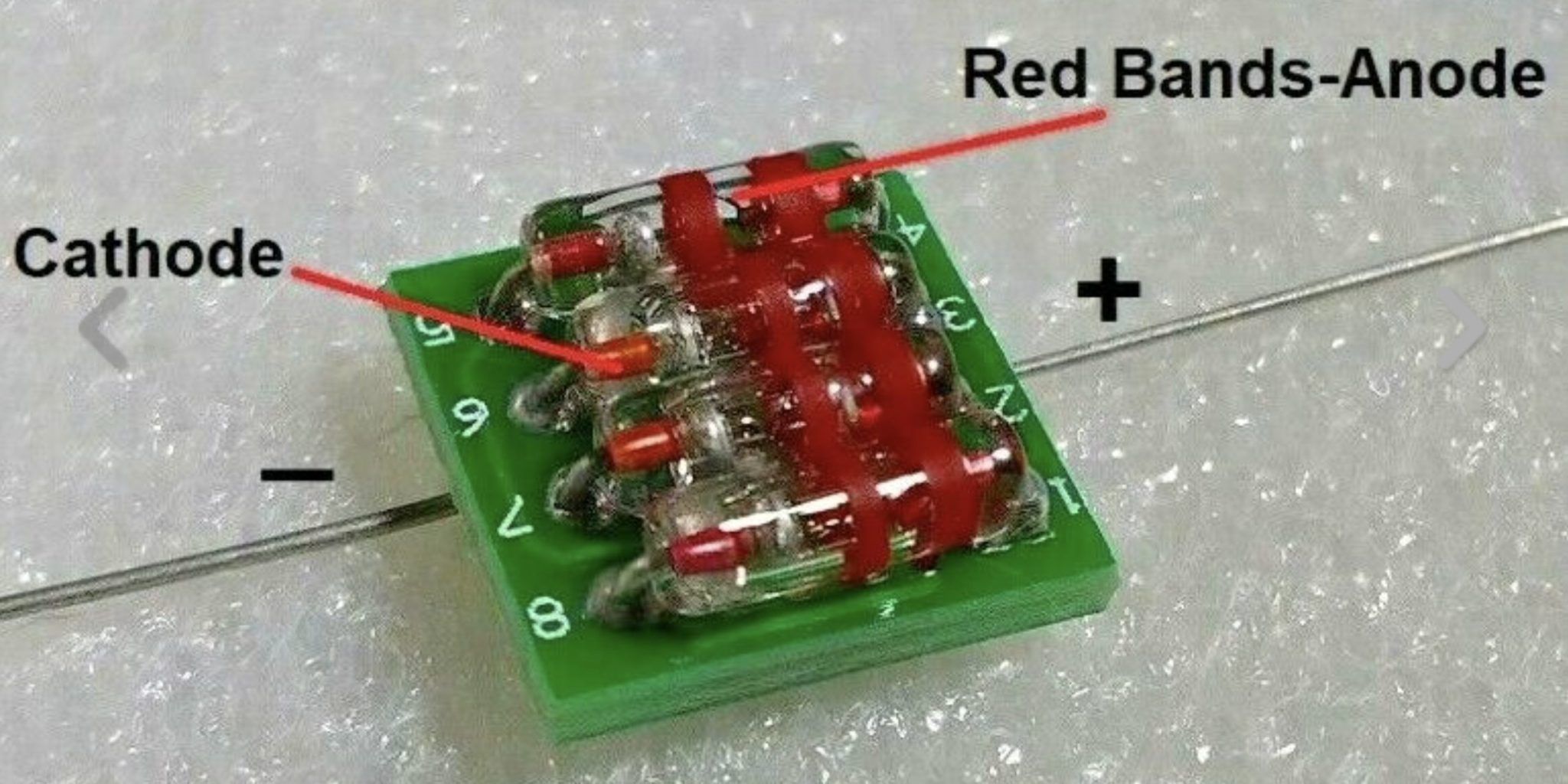
Now, it’s true that connecting resistors in parallel will decrease the total resistance, but let’s look at a typical crystal radio circuit:
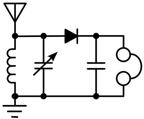
This circuit uses high-impedance headphones or a high-impedance earphone because there is no powered amplifier. The only power comes from the received radio wave itself. This means that very little current will be flowing in the circuit, so there’s really not much to gain by decreasing the “Diode Resistance.”
So, to answer my own question, no, I don’t think that paralleling diodes in a crystal radio circuit would make it work noticeably better.

The Long Island CW Club has turned into much more than a place for hams to learn Morse Code. It really is an online amateur radio club. Their Zoom rooms host talks on a wide variety of topics, and their mailing list has become a forum for less experienced hams to seek out the advice of those who, shall we say, have been in the hobby for a while.
A recent thread, Understanding Basic Electronics, caught my eye. It has a number or resources to help the new ham learn electronics. Of those, there’s one I really like, How Transistors Work – A Simple Explanation. It has explanations for how both bipolar junction transistors and field-effect transistors (FETs) work.
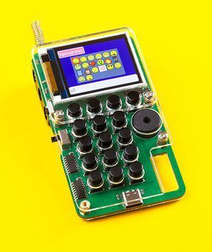 Chatter is an amusing little device that uses LoRa to send encrypted text messages. I’ve often thought that a device like this, but operating on the amateur radio bands, would be a killer app for amateur radio.
This particular device is kind of expensive at $132. Not only that, it comes as a kit that you have to put together yourself. Both those being the case, I don’t see this becoming a big seller. It is amusing, though.
I haven’t checked in with the Ham Messenger developer lately, so I don’t know how that project is going. For folks with a license, though, I’d still recommend that that is the way to go. Of course, since Ham Messenger uses amateur radio frequencies, the messages can’t be encrypted. It seems a bit silly that you can encrypt using an unlicensed service, while you can’t with amateur radio, but them’s the rules.
From Southgate ARC:
 Talks from the Ham Radio Village at DEF CON 29 released
The amateur radio talks given in the Ham Radio Village at last year’s DEF CON 29 event are now available on YouTube. The talks include:
Watch the talks on the DEFCON YouTube channel.
So, a couple of days ago, a guy in our club posted to our mailing list that he was thinking of starting a group buy for the (tr)uSDX transceiver and included a link to the video below:
Here’s a description of the little transceiver:
The (tr)uSDX is a 5-Band / Mulitmode QRP Transceiver in Pocket Format (90x60x30mm – 140g). It features a highly efficient Class E PA and Supports CW/LSB/USB and AM/FM. Right now it covers 80/60/40/30/20m and in Future there will be support for 17/15/12/10m as well.
It is supplied with an OLED Display, onboard Mic, (tiny) onboard speaker and for improvised QSO onboard PTT Key can be used as emergency CW Key. Further on, the (tr)uSDX has a (Micro)USB CAT and Programming Interface, and while it produces typically 5W @ 13,8V Power Supply, it can create 0,5W Output from 5V USB Supply alone.
Typically it draws 80mA on RX (with MS5351 – less with Si5351) and 500mA on TX @13,8V and typical 85% PA Efficiency. It is supplied with OnBoard SWR Bridge and Voltage/Current measurement Hardware, to help in tuning and operation.
Talking about the on-board test equipment, here’s a short video on how that works:
The guy says that if we do a group buy, they’ll cost about $60. That seems pretty cheap, since in single unit quantities, they’re selling for closer to $100. Here’s a video of the designer unboxing a kit from one of the Chinese suppliers:
I don’t know where the guy is going to be making the group buy, more than a dozen club members have signed up so far. I need another project like I need a hole in the head, but I’m going to get one, too.
![]()
![]() All three articles in this post are from Electronic Design….Dan
All three articles in this post are from Electronic Design….Dan
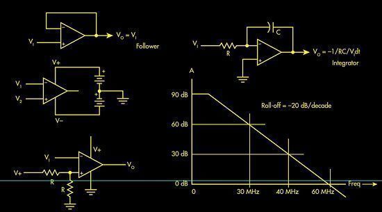
Op amps are the basic building blocks for much of linear circuit design. You probably learned about them in college and even designed some products containing an op amp. As an electronic engineer, you will at some point in your career probably need to design a linear circuit.
When you need to take accurate timing measurements in hardware without overloading a microcontroller, the signal measurement timer module (SMT) in the Microchip16F1619 PIC microcontrolleris perfectly suitable for this application. The SMT module captures features of a signal such as Period and Frequency, among others. This design measures input frequency signals within the range of 8 Hz to 10 MHz, and Period signals within the range of 0.1 µs to 125 ms…..more
Antennas are much more than simple devices connected to every radio. They’re the transducers that convert the voltage from a transmitter into a radio signal. And they pick radio signals out of the air and convert them into a voltage for recovery in a receiver.
Typically taken for granted and left for the last minute in a design, antennas are nonetheless critical for establishing and maintaining a reliable radio connection. They may look complex and enigmatic to most engineers, especially EEs working with wireless applications for the first time—not to mention that they come in a seemingly infinite variety of sizes and shapes. However, a brief review of the essentials can help allay any design worries….more
With the advent of the nanoVNA, S- parameter measurement is now within reach of most hams. What are S-parameters? Watch this video and find out. Most hams probably don’t need to know this stuff, but it’s pretty cool when you do know it.
They don’t make films like this anymore. I’m guessing that they don’t make crystals like this anymore, either.
Fluke meters are arguably the Cadillacs of the test and measurement world. In this video, Dave explains why this is so. Although he gives eight reasons why Flukes cost more than other meters, I think that the most important is measurement confidence. You just feel more confident about the measurement when you’re using a Fluke.
N3JT posted this to the CWops mailing list, and I thought it was just hilarious.
This video has been making the rounds lately. It presents a very interesting explanation of how electrical energy flows.
I am an unabashed Begali fanboy. Here’s a peek inside the Begali factory.
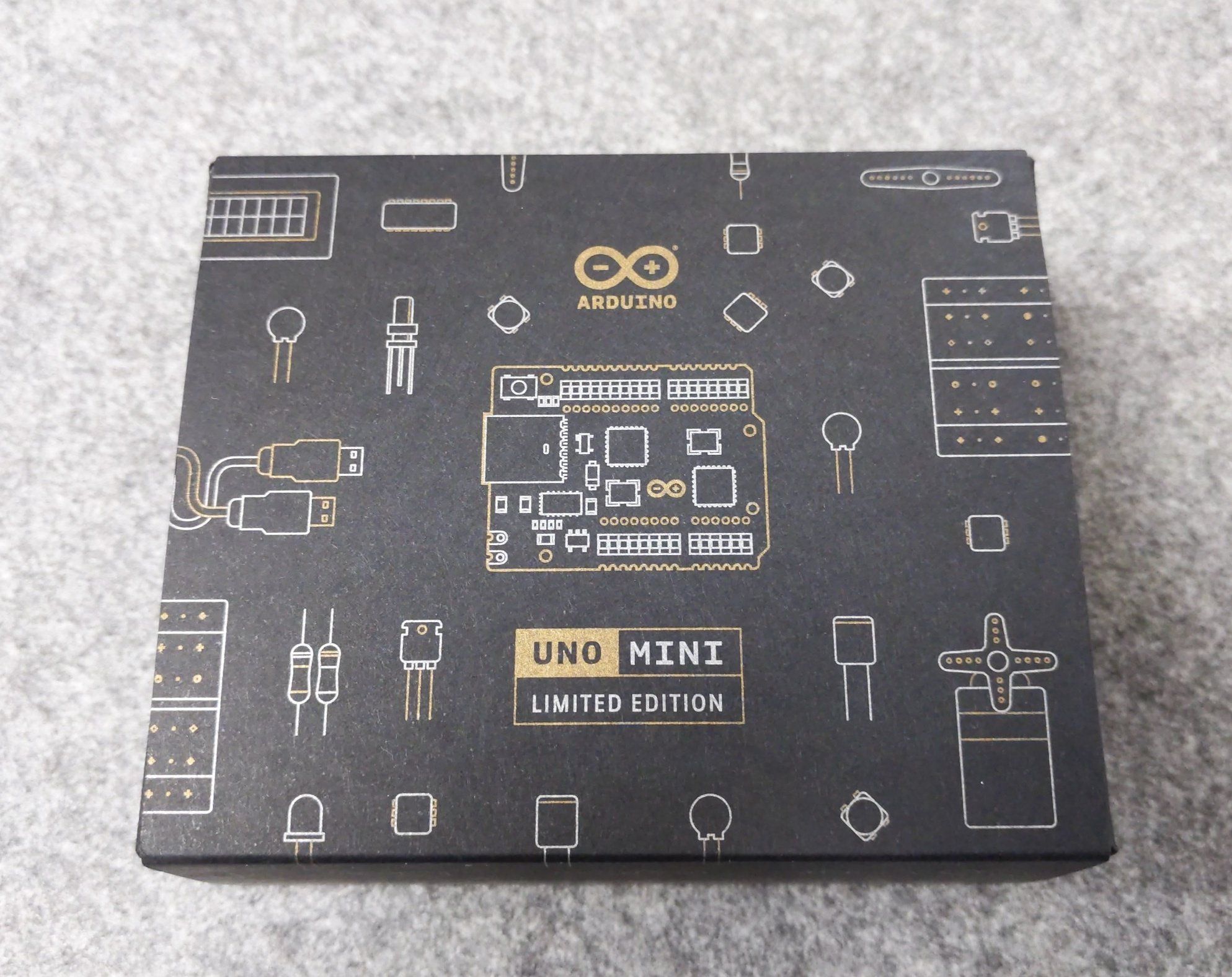
About a week ago, this Tweet flashed across my feed:
Happy 10 million UNOs, @arduino
My first UNO was one of the things motivating me to get into electronics as a child. As an older child I’m now happily studying Computer Science in Uni and you are one of the reasons. Very happy to hold this in my hands now!
I retweeted and added the comment, “#hamradio needs something like the Arduino.” The more I think about this, the more I think this is true. An UNO is something that is affordable and simple to set up and something that kids and newcomers can have fun with almost right out of the box.
Someone commented:
Yeah, if only we had a software defined transceiver and does-it-all software. Oh… wait… analog.com/en/design-cent… and gnuradio.org. Point being, we have the hardware + software – we just need to popularize it.
This is not a bad idea, but I think that this solution is still too expensive (a PLUTO SDR costs more than $200). And, GNURadio is certainly not for beginners. My reply was:
A PLUTO costs $200. An Arduino costs less that $20.
To which, I got this reply:
OK. For a transmitter, how about $35 for a Raspberry Pi + github.com/F5OEO/rpitx? For a receiver, $30 for rtl-sdr.com/buy-rtl-sdr-dv…
I said:
Now, you’re getting closer, but you can’t just dump this on them and expect them to magically create a working set. They’ll need some instructions and/or some coaching.
And my friend’s reply:
We’re in violent agreement. Arduino didn’t succeed because it was good hardware, it succeeded because of the vast ecosystem – books, classes, video tutorials, etc. We need the same thing for Software Defined Radio, especially “training wheels” for GNU Radio.
So, my question—or challenge, really—is how do we come up with something that lets beginners get started in radio for less than $100 and offers a similar experience to the UNO?
 Homebrew cootie key cuts through QRN, QRM
A couple of days ago, I worked a guy who said he was using a homebrew sideswiper, or cootie, key. I looked him up on QRZ.Com, where he featured a photo of his key (see right). After seeing this photo, I tweeted:
Just worked a guy using this homebrew cootie key. It really cuts through the QRM and QRN.
I included the photo in the tweet.
That really caught the eye of my followers. More than two dozen have either liked or commented on it.
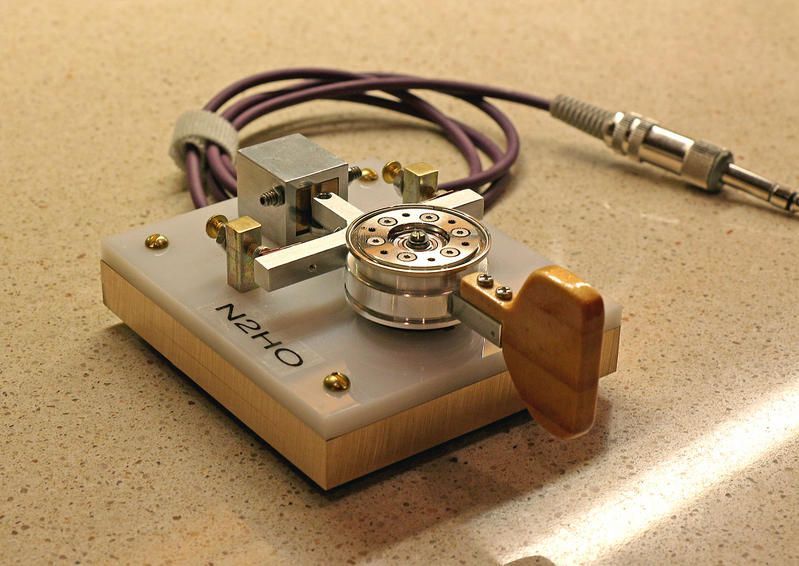 Last night, I worked a fellow who also noted that he was using a home brew paddle. He said that it was similar, but not exactly like the paddle built by N2HO (shown at left).
The unique thing about this key is that it uses the magnet and bearing from a hard disk drive. I don’t know if or how the magnetic tension is controlled, but I think the design is quite unique.
In the past week or so, I’ve worked stations with fun callsigns. the first is AI5IN. Joe’s call not only spells a word, but it is palindromic, if you consider the sequence of dits and dahs.
Last night, I worked K5EMI. Bill didn’t mention why he chose this particular call, and I wonder if he knew that EMI is an acronym for electromagnetic interference. I may have to email him about that.
 Back to Basics: Impedance Matching By Lou Frenzel, W5LEF
The term “impedance matching” is rather straightforward. It’s simply defined as the process of making one impedance look like another. Frequently, it becomes necessary to match a load impedance to the source or internal impedance of a driving source. A wide variety of components and circuits can be used for impedance matching. This series summarizes the most common impedance-matching techniques.
The entire series is available as a downloadable ebook.
While I’m not sure, I’d guess that something similar happens on 160 meters or even the HF bands….Dan
 AM Radio ‘Flutter’
Sometimes I like to listen to a couple of AM radio stations that transmit from southern New Jersey, which is rather far from here on Long Island. Their signals are pretty strong during the daytime but now and then there is a rapid in-and-out fading effect, which sounds very much like a flutter.
I’ve sometimes heard that same effect when listening to shortwave radio and I initially assumed it was an ionosphericphenomenon but now I don’t think so. There seems to be an alternative explanation.
I haven’t tried these yet, but they look like fun….Dan
There’s plenty of low-cost hardware out there feasible for implementing deep learning training and (especially, along with being your likely implementation focus) inference, as well as plenty of open source (translation: free) and low-priced software, some tied to specific silicon and other more generic. Tying the two (hardware and software) together in a glitch-free and otherwise robust manner is the trick; select unwisely and you’ll waste an inordinate amount of time and effort wading through arcane settings and incomplete (and worse: incorrect) documentation, trying to figure out why puzzle pieces that shouldfit together perfectly aren’t.
That’s where Google’s AIY (which stands for “Artificial-Intelligence-Yourself,” a play on DIY, i.e., “Do-It-Yourself) Project Kits come in. They’re targeted at hobbyists and professionals alike: in Google’s own words, “With our maker kits, build intelligent systems that see, speak, and understand.